Reproduced from “The News”, Saturday September26th, 1992

After surviving the bombing of his home and his Portsmouth workplace, Ray Wells was one of only two pilots in his wartime Spitfire squadron who came through alive. Now secretary of Langstone Sailing Club, he talked to Robert Lindsay about his war years

I was a British Rail clerk at the Fratton Road depo and was standing out on Goldsmith Avenue when it happened. It was just a lone raider on a day-time raid.

We saw this plane but there was no air raid warning or anything so we all wondered what was happening. We were looking up at it and we saw something detach from the fuselage and we thought “What the hell is that?”. Then we realised what is was and went flat on the ground.

It fell on the end of the freight depot and damaged it quite severely, one or two people were injured but no one was killed.

I used to live in Lichfield Road at Copnor which was heavily blitzed. Each cluster of bombs made a kind of whistling screech as they fell through the air. I can remember being in the shelter there counting the number of salvoes you could hear. I got up to 80-odd! The landmines didn’t make a noise because they came down on parachutes.

Our house was damaged and Cuthbert Church was ruined and had to be totally rebuilt.

By the time I was 18 in September, 1941, I had eventually managed to get into the Air Force. At that time, after the Battle of Britainm everyone wanted to join. Though I was only a lowly clerk I thought I would have a go and got through.

I never thought I would attain the heights of a pilot, but I found I was just as good as the university graduates and the doctors and dentists I was with.

After training in America and Britain, I was finally posted to 19 Spitfire Squadron in August 1943.

I was with 19 Squadron all the way through D-Day and the war through Belgium and Brussels. I flew 115 operations. I was a bit over the top because you were only supposed to fly about 20 ops on a tour then you were meant to be give a rest.

There was myself and one other chap. We were the only two left out of a force of 90-odd pilots, The rest were either killed, prisoners of war or just didn’t make it through for other reasons.

The worst bit was the waiting around to fly. The actual flying was all right. It was the bit between that got a bit strained. You were losing people all the time and were wondering if you were going to be next.

I had a few dog-fights all right. I shot down  four German fighters, Focke Wulf 190s. I was damaged twice, both times by flak, once over Le Havre when it was enemy hands and once right over Germany, but I managed to get back all right.

On a rest

Just towards the end of the war, to give me a rest, they post me to the RAF Film Production Unit at Pinewood Studios. We took cameramen up over Germany so that they could take stills and newsreel film of the bombing.

I even had to take them to film out men crossing the Rhine. I had to fly under out own artillery fire at about 200ft and then turn to follow the river, tilting the aircraft so that the cameraman could take his shots out of the window! I was supposed to be on a rest!

After the war I want back to British Rail as a clerk again and I worked my way up so that by the time I retired I was a project officer on computers.

I was given the opportunity to carry on flying, but it just wasn’t my cup of tea. They needed people from universities. I’d just been to Portsmouth Polytechnic where I’d trained to be a pattern-maker in the dockyard. I didn’t have the right background.

Man Maths

Just before the twins were born in 2015, I decided that we needed a spare family car – we had an one, but it would be useful to have 2 cars capable having kids in the back. A bit of googling told me that the standard Audi A6 isofix bars bolted straight in to the back of the RS6. And I am a bit of a petrolhead – and the cars were cheap! A Plan started to come together…..

Lots of looking at the RS6s for sale at the time – many clearly in very poor condition, with some being crazy money. Eventually I came across this one:

What stood out about this one was that it seemed relatively decent and untouched, but even better, was black but didn’t have the white leather interior. I don’t like white leather – instead, this one had the black alcantara with aluminium trim interior, which is a rarer combo and I think it really works! So a few thousand £ later and the learning journey started. I’d read all about the weaknesses of these cars and that all the solutions are – but I figured it wouldn’t need ALL of them doing – would it?

Engine Out – Part 1

Eventually I found the torque converter wasn’t locking up correctly, despite the gearchanges still being silky smooth. I did a gearbox service with new oil and filters – the oil came out looking manky. The TC valiantly tried to lock up, but just couldn’t manage it.

Audi claim these gearboxes are sealed for life, but ZF themselves make a service kit for them and it’s well known that an occasional gearbox oil change is required to make the gearboxes last – what Audi really mean is they’re sealed until the warranty expires. So I bit the bullet and removed the engine to do the torque converter and gearbox – for the first time. I’ve built or rebuilt loads of things before – but never in what I’d call “modern generation” cars. What I mean is in a car where everything is designed by CAD and crammed in, but gives no acknowledgement of needing to service things! It is a complex and tight fit in there. But we got there in the end and while it’s a lot of work, it’s actually not hard as long as you’re patient and methodical

That job all went OK – you can see the new gearbox in the pic above – and bolted it all back together. The car ran well – but now it was loosing a little coolant! This was the moment where I learnt that the list of things to look for on a C5 RS6 are not “maybe” things – they will happen, it’s just a question of when. The little plastic pipe that connects the oil cooler to the engine block had fractured – the notorious “bufkin” pipe. So it was time to pull the engine again! Argh!

Engine Out – Part 2

This time, I decided “lesson learnt” and went in to it much more fully, including not just replacing the bufkin pipe with the lovely alloy machined one you can get, but replacement intercoolers (Audi ones always leak, even when new), shortening one of the hard cooling pipes that prevents you from removing the RHS rocker cover unless you remove the engine (what moron designed that!)

Replaced the DRC entire DRC setup (another when, not “if” thing that fails) with Koni shocks – and had all the steel suspension arms and springs powdercoated too:

At the same time, also had the turbos rebuilt with new cartridges by Owen Developments. Stock – other than upgrading the thrust bearings in the turbos to 360 degree ones for better longevity. Also used the opportunity to replace the plastic shoes on the cam adjusters – they are known to wear at about the 80K mark and if they disintegrate, it causes a right mess.

I’ve sort of lost track of everything I did to it – it’s all noted down in a spreadsheet somewhere – but I also tidied up the engine bay and replaced the inlet hoses (that always collapse) with some nice silicone ones. I think it looks smart – I’ve actually replaced the black inlet ducts with carbon ones that match the air filter covers now – they are lovely.

Brakes

At some point, I decided to redo all the brakes. New rear calipers are easy to source, but the fronts are a bit more special – so I had them rebuilt. With hindsight, I think I could have saved myself a chunk of money by doing it myself, but the convenience of having someone else do it was appreciated:

I think the calipers came out OK, although I think I overpaid:

You can see I both powdercoated the backplates at the same time, and also replaced the lower wishbones with new:

That Plastic Bit

There’s a really nasty plastic air duct at the front of the cars, that channels air through the oil coolers. It’s simultaneously floppy and yet also brittle – and annoyed me every time I went near it. So I decided to make a new one out of some nice NS4. The hateful plastic bit:

Starting to make a new kit of ali parts:

Assembled on the workbench with the old bit behind:

And on the car. I think it came out OK:

Today

That’re pretty much where it is today. All the stuff that they need doing – is now done, and I can by and large enjoy the car. Currently waiting on some new wing mirror glass to arrive and is due a bit of a service – but the effort above was all worth it and the car all just works now.

A bit of background

I built this Spyder back in 1997 with a Renault 25 V6 Turbo motor & UN1 Gearbox. It was good and I was a fairly early adopter of building a kit car with an EFI motor, especially turboed. Image
Image
Image 
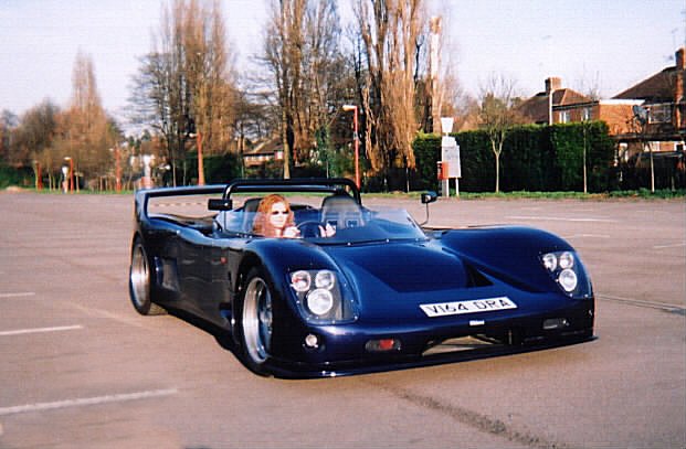
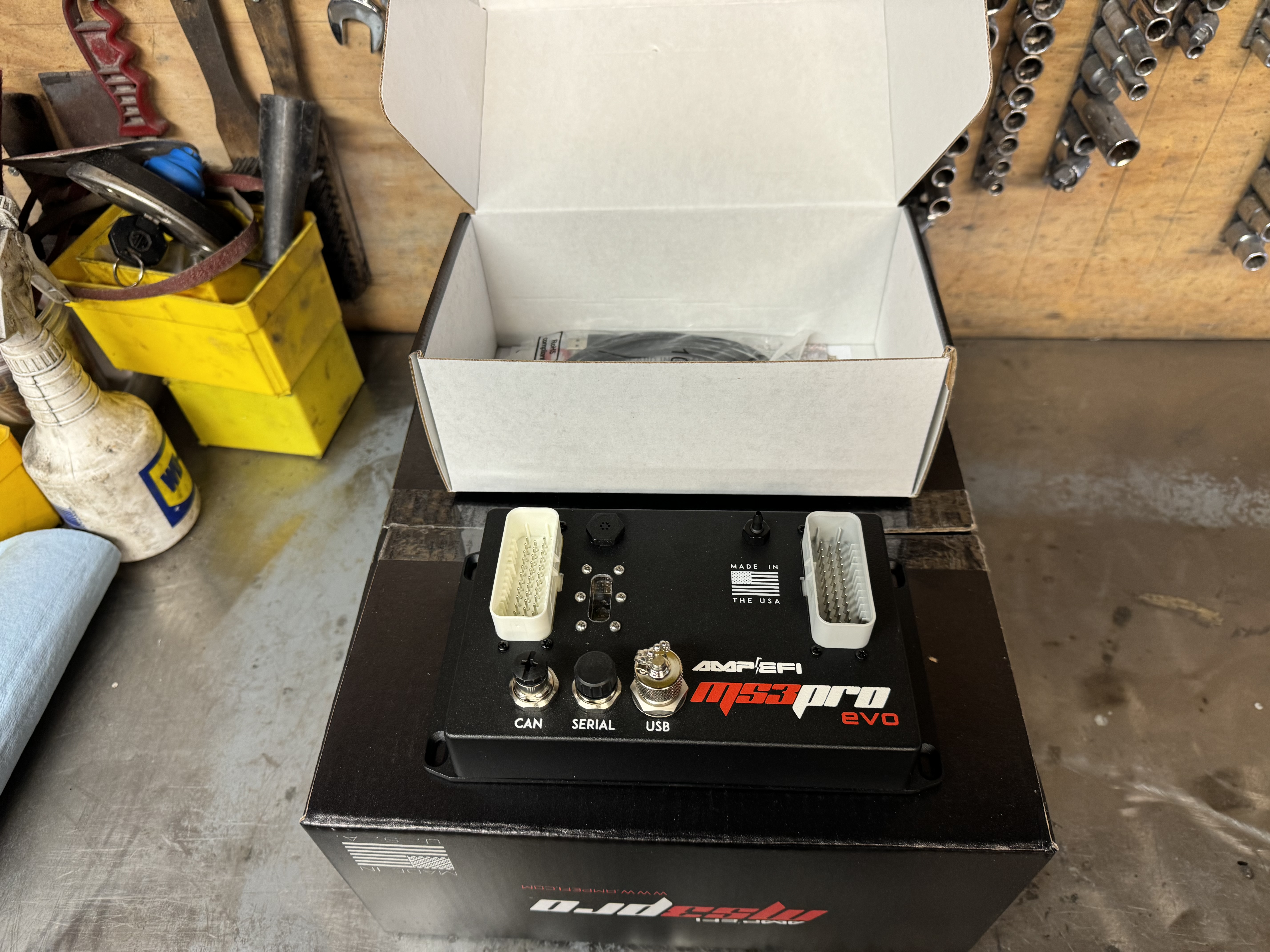
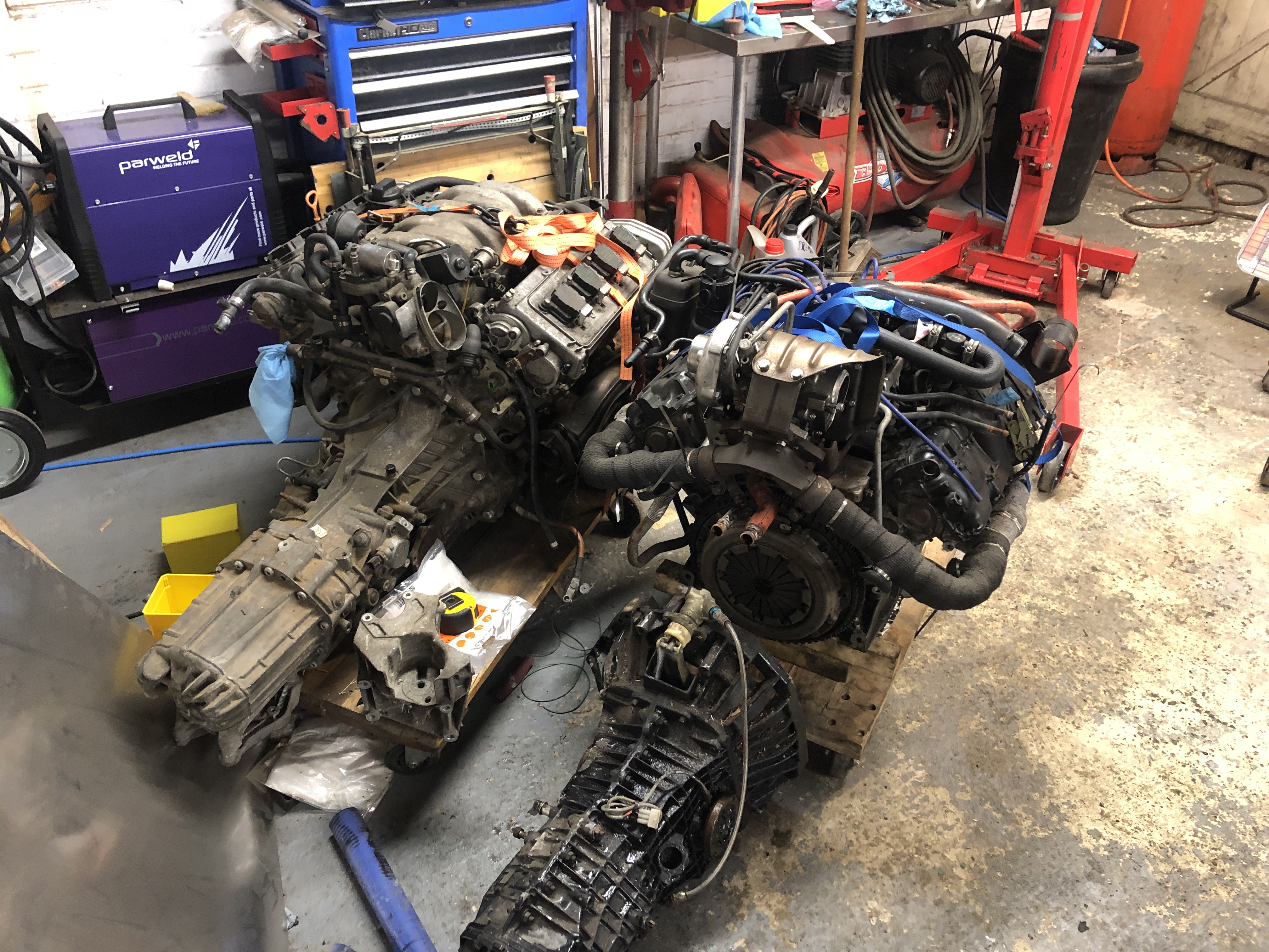
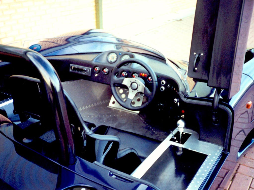
It always ran well – but time passes and I decided a few years back to re-engine it. I bought an engine, gearbox, custom flywheel & clutch for it – and then parked it for another few years…

Getting Started

Roll on 2021 and I decided I really must make a start on actually doing this conversion. So I now had:

  • an AHC Audi V8 Motor
  • and a GVC 01X G-speed Box

Image 
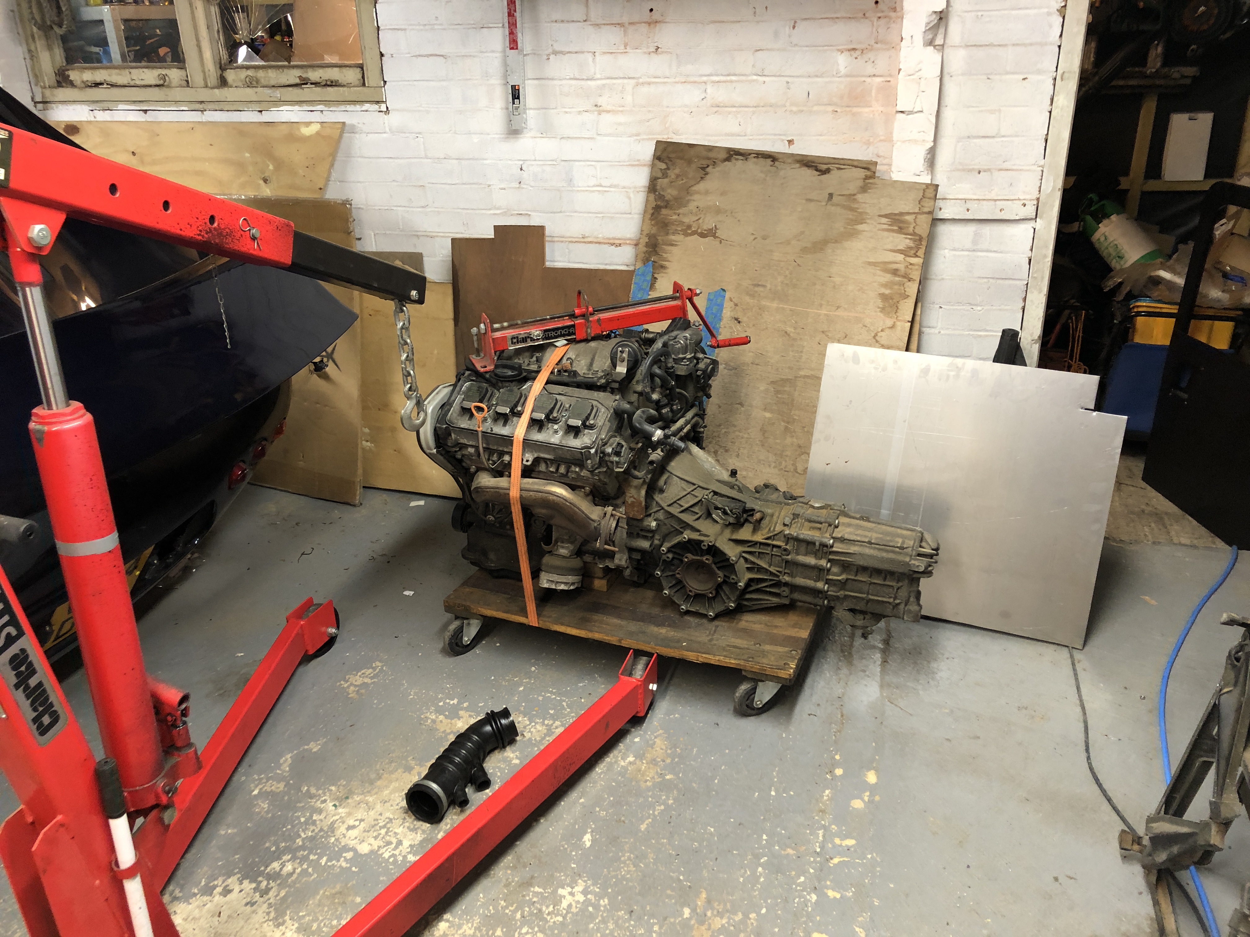
Time to take the old engine out: Image Image 
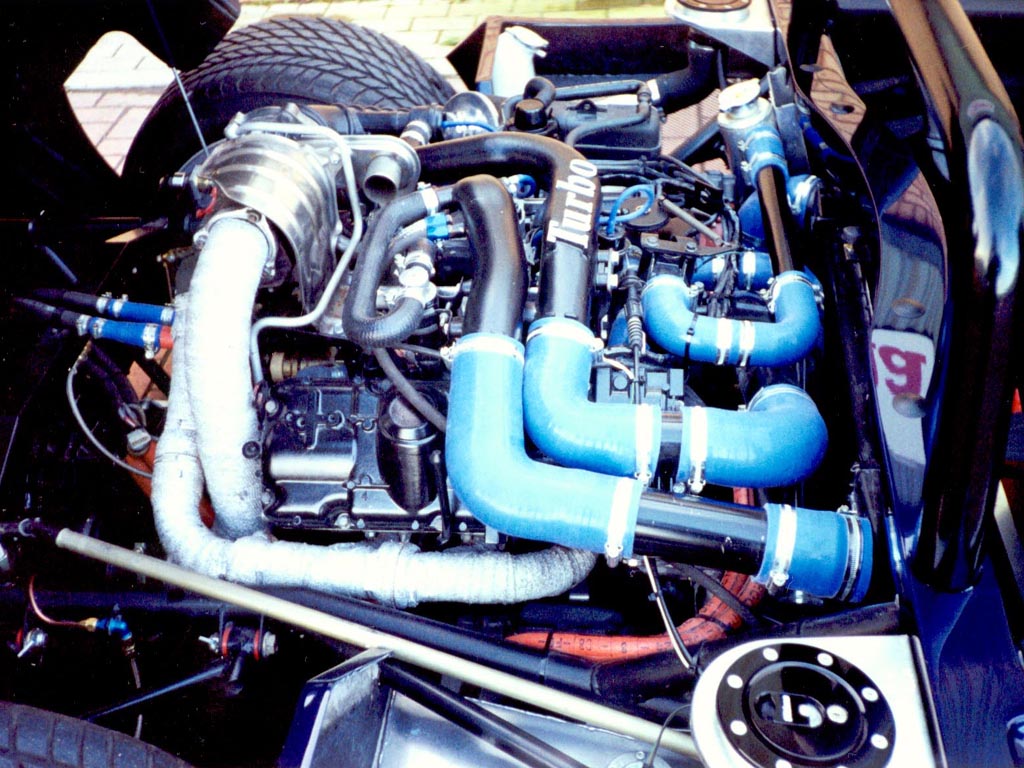
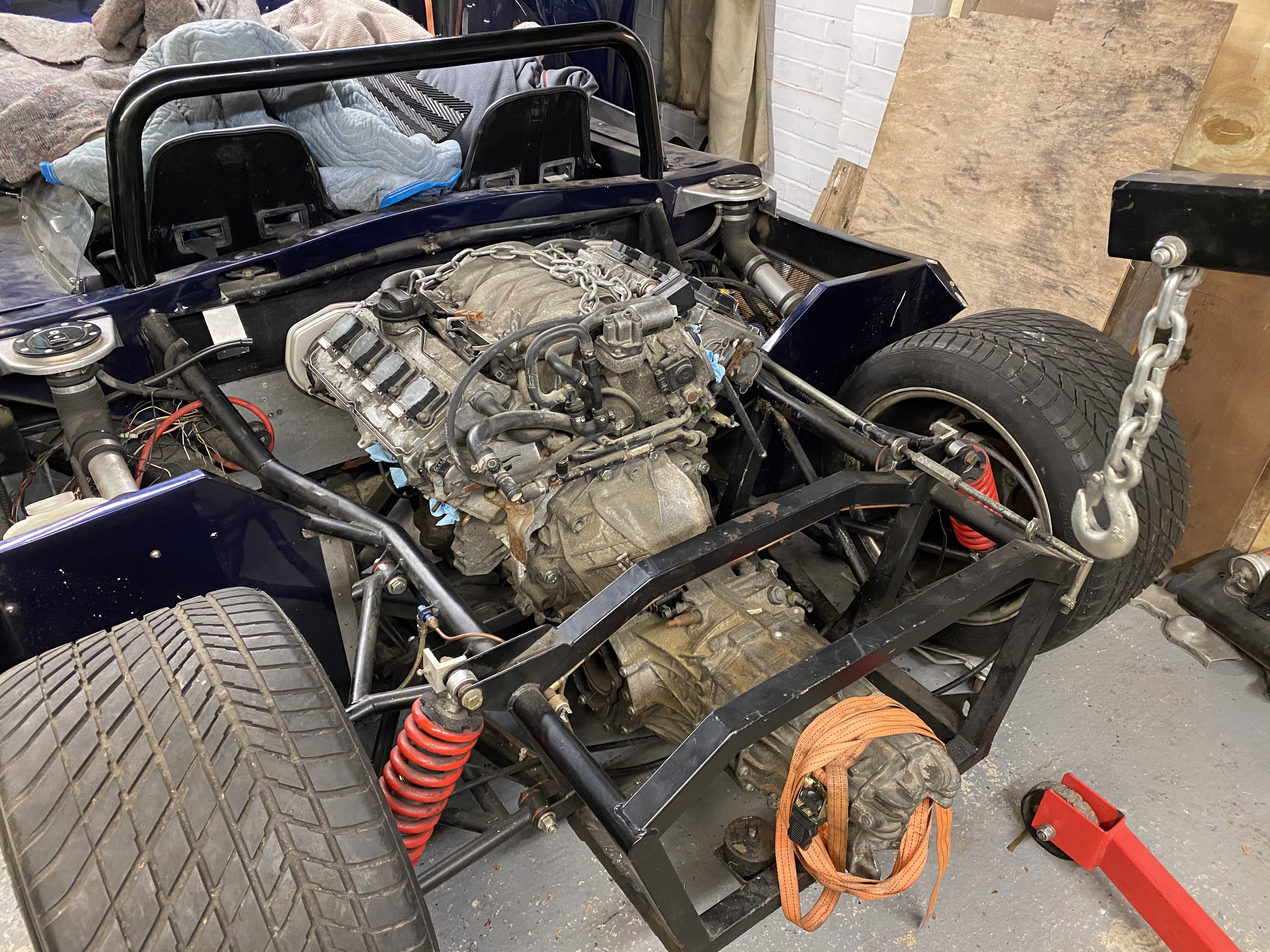
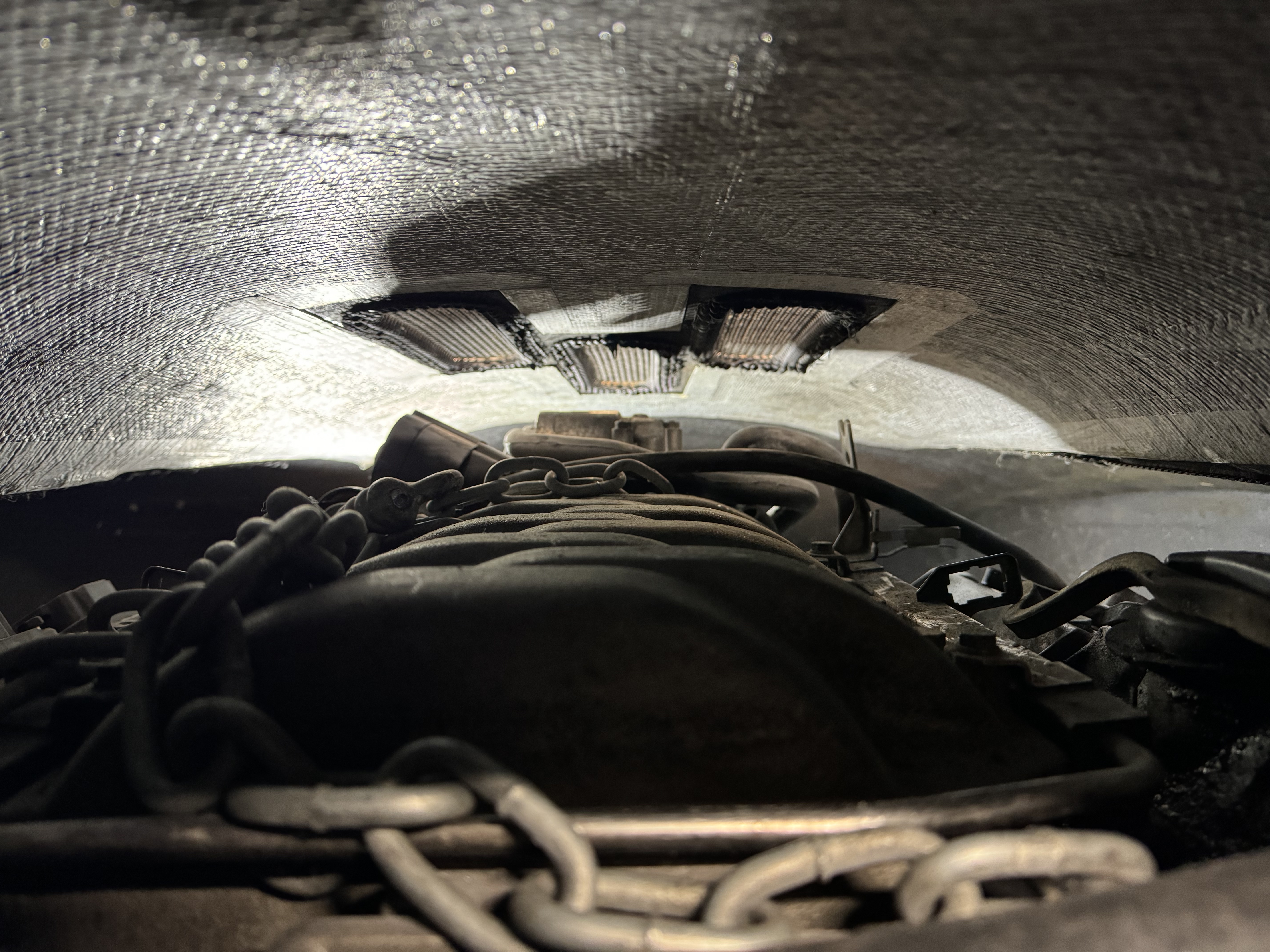
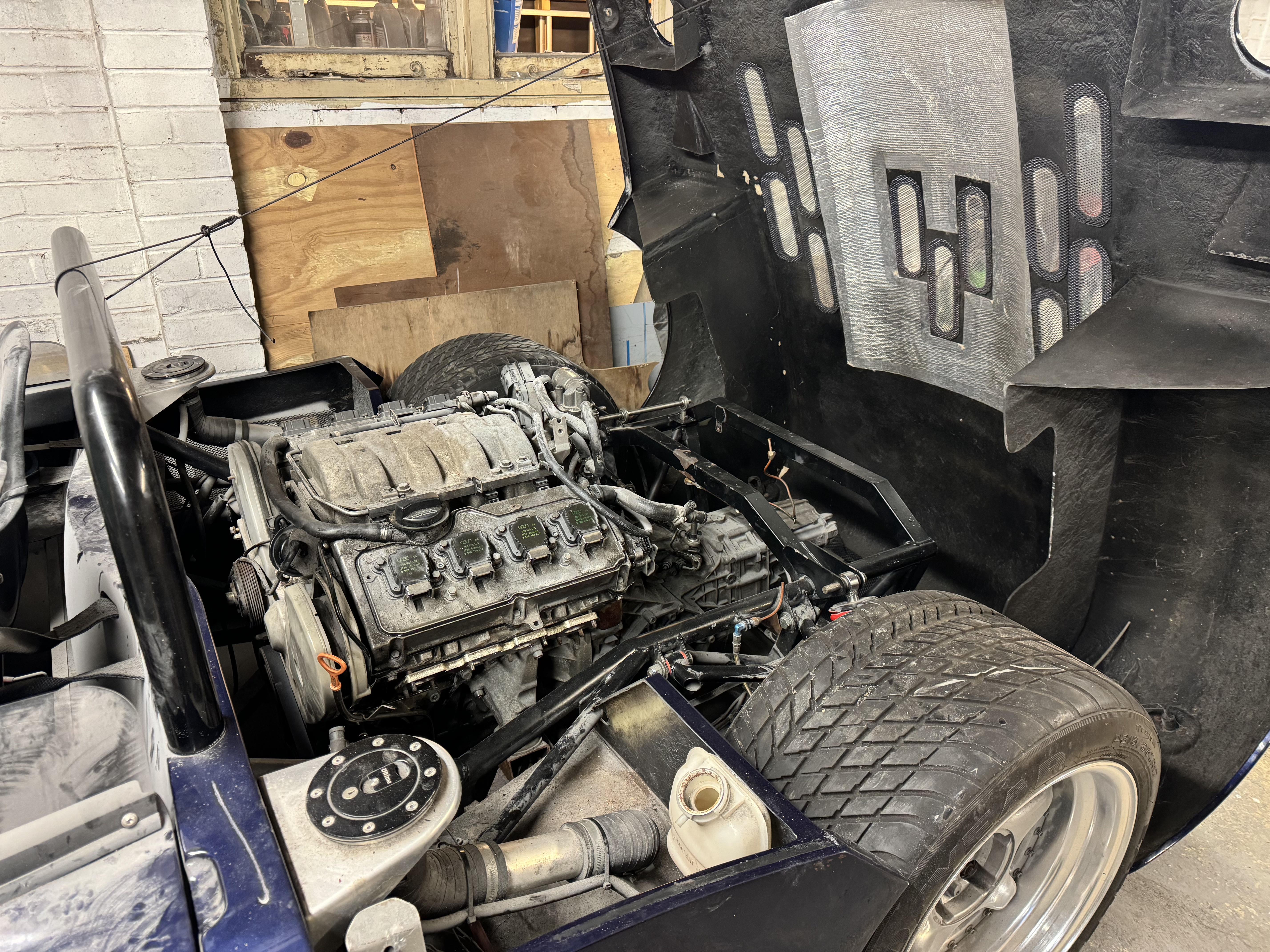
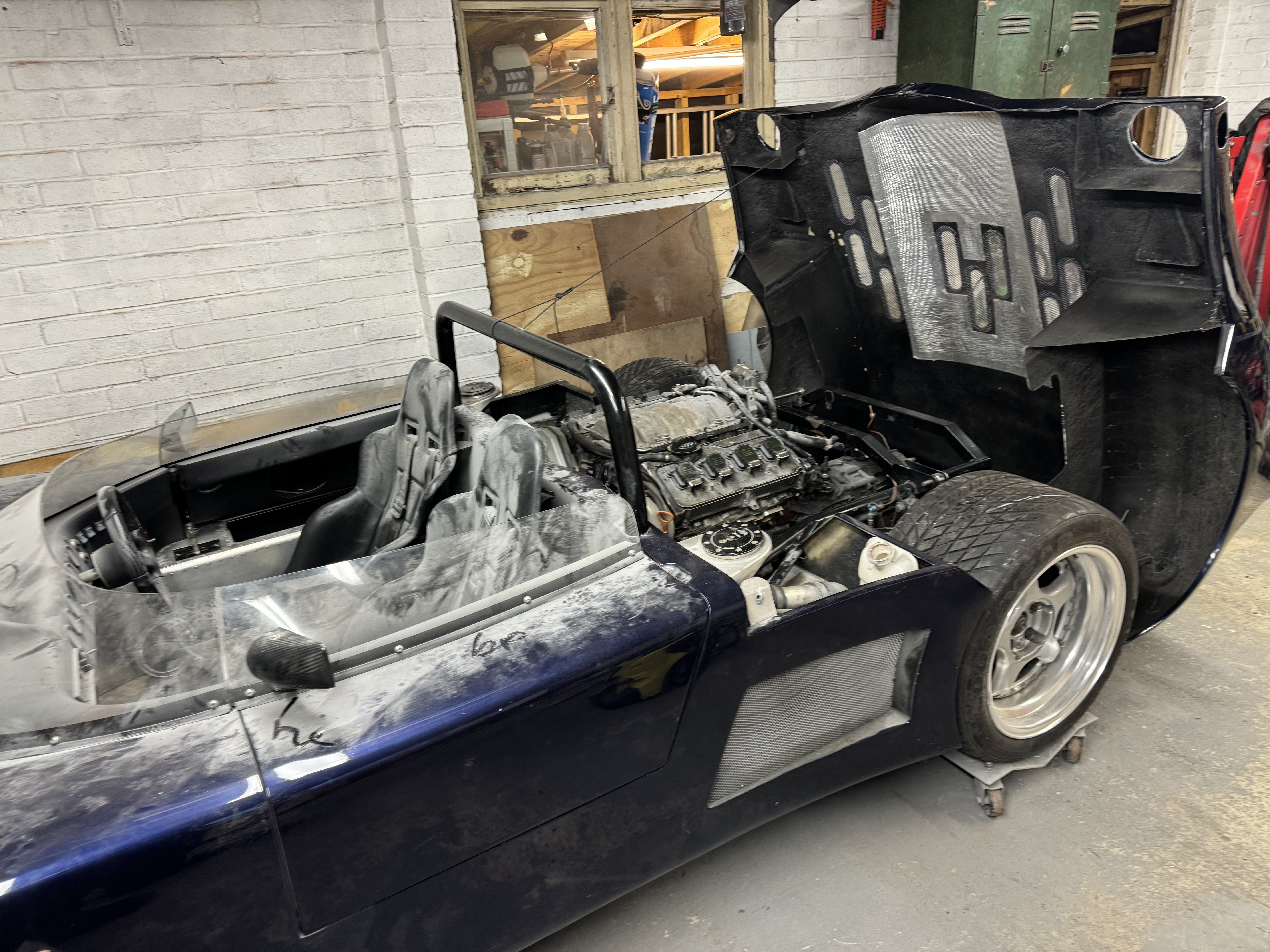
Almost twice the horsepower, but hardly any bigger: Image

Chassis Modifications.==

Still learning the new welder, but seemed to go OK: Image Image

Engine looks like it was made to fit, good clearance all round on the chassis and body – which is excellent, I don’t think anyone has tried to squeeze one of these motors in to a spyder before, they have less hood clearance than the sports/gtr/can-am. Sump protudes about 15mm out the bottom – which is a less than the old motor did and also shed loads less than a SBC would.

The motor was sitting on wooden blocks in the new chassis in this pic while we check clearances: Image 
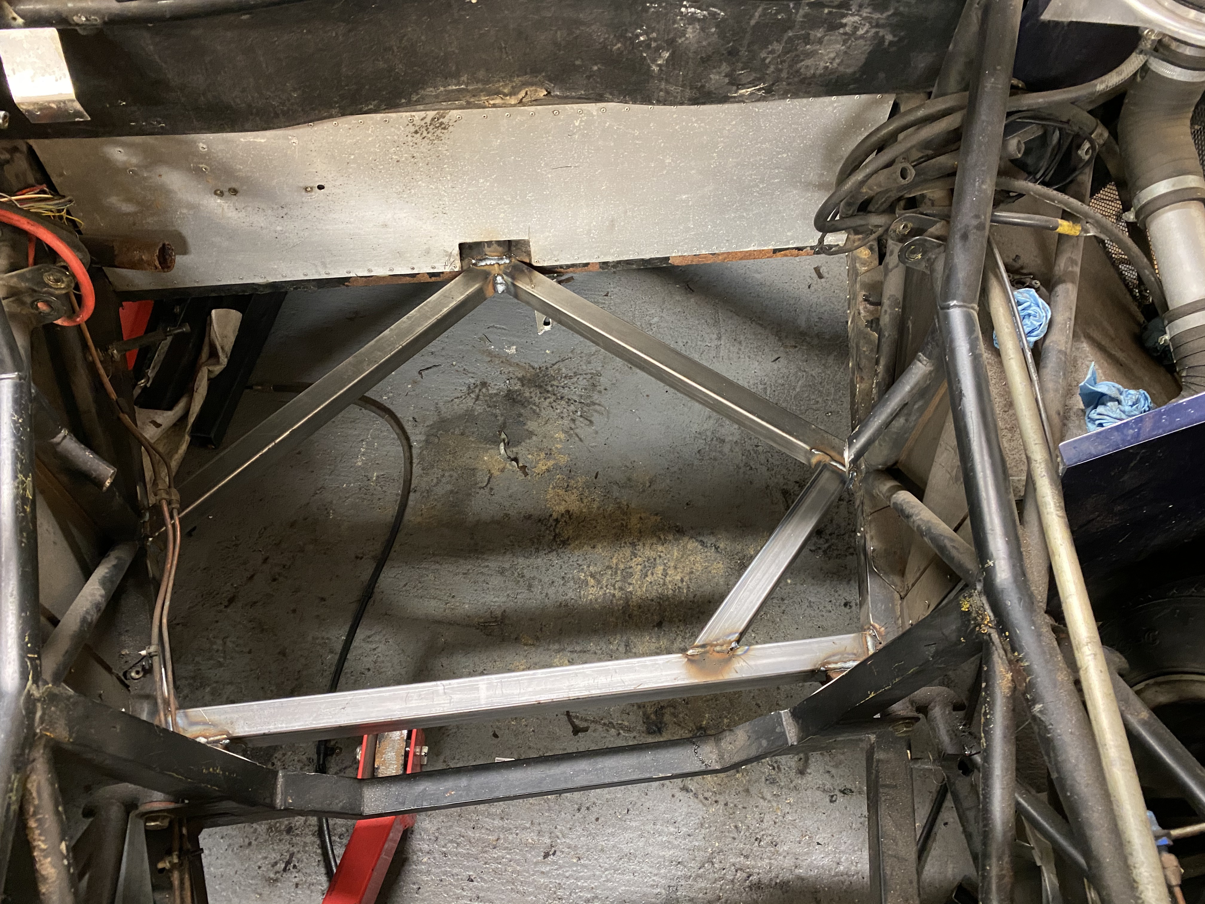
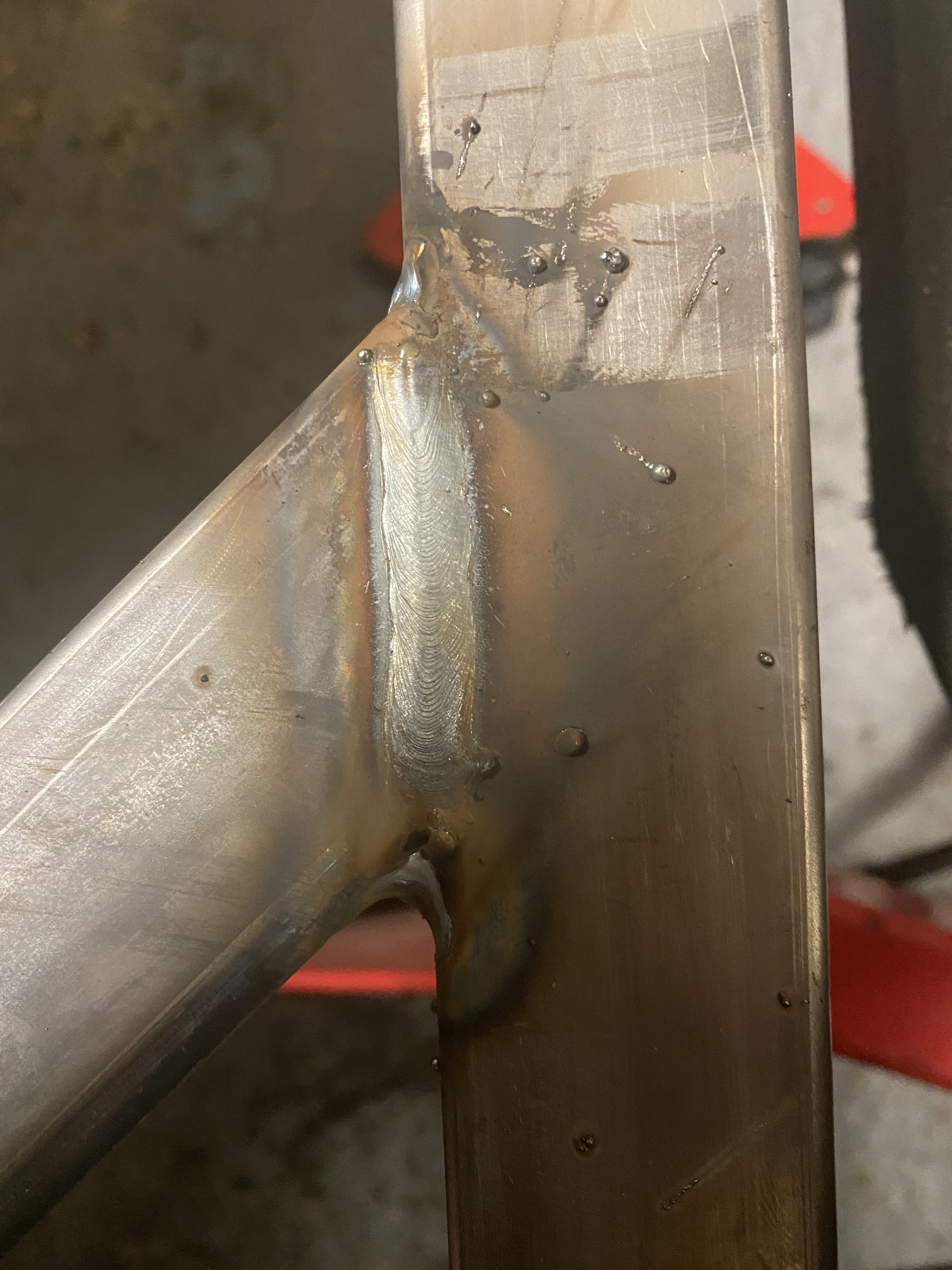
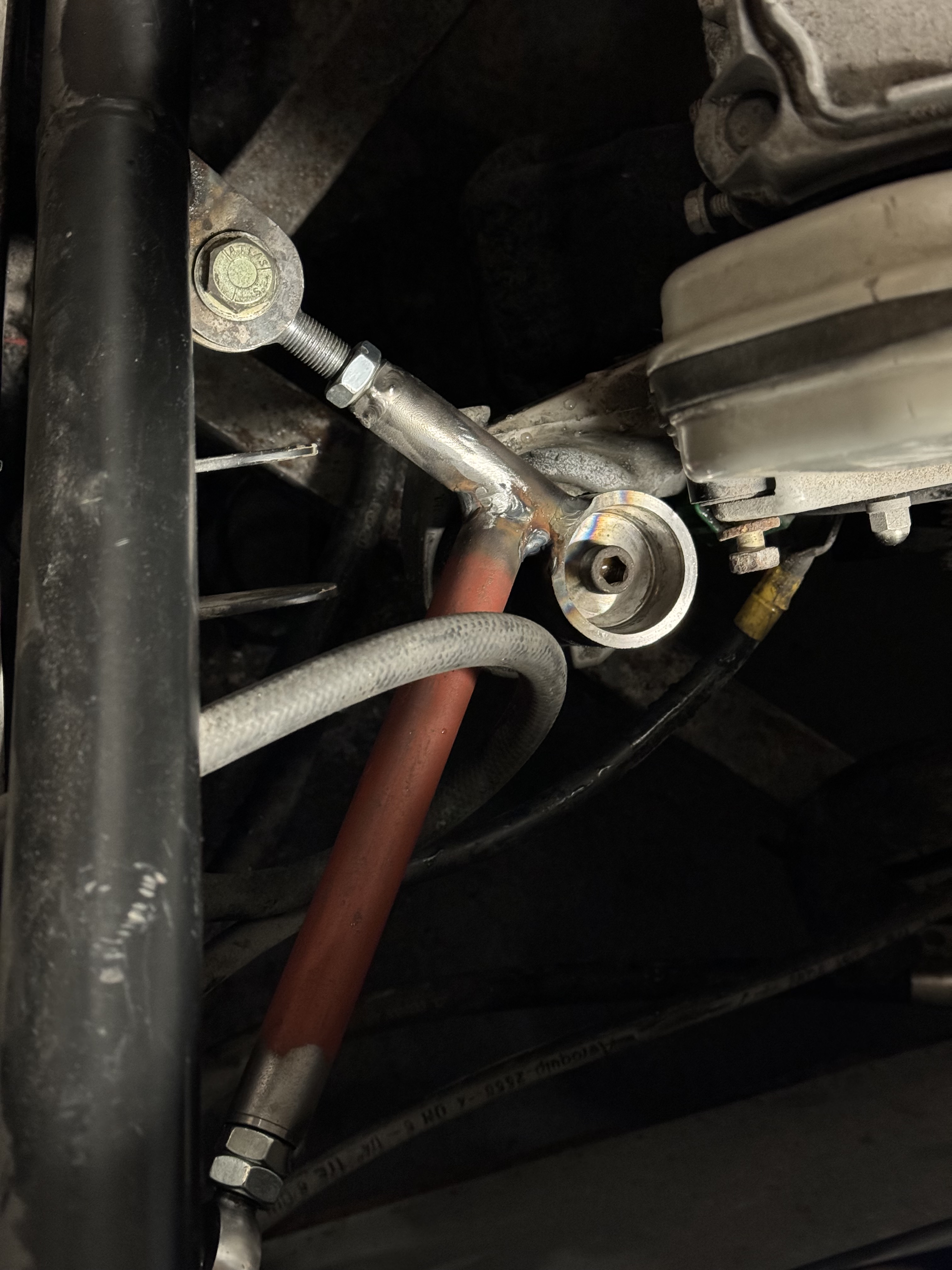
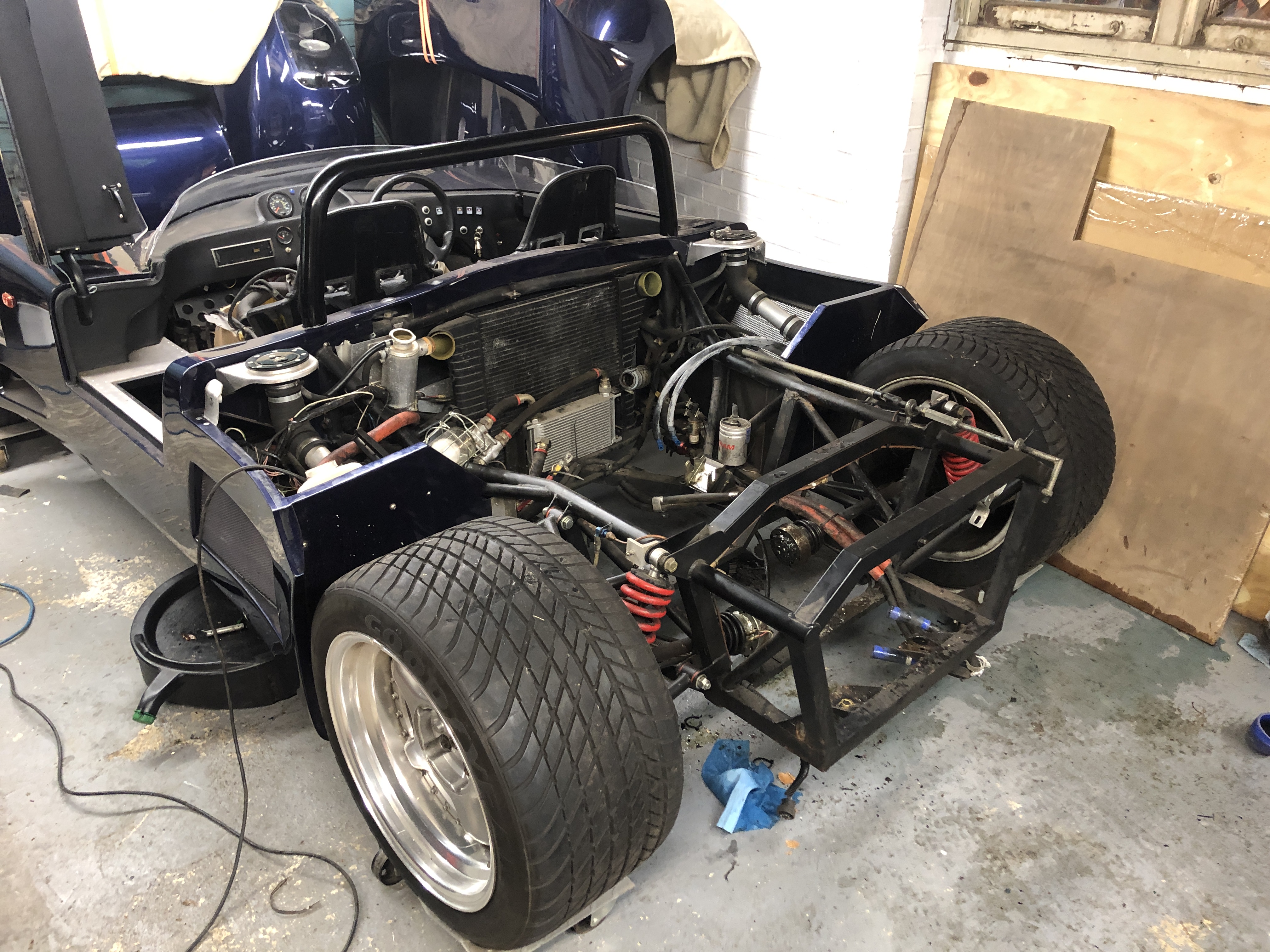
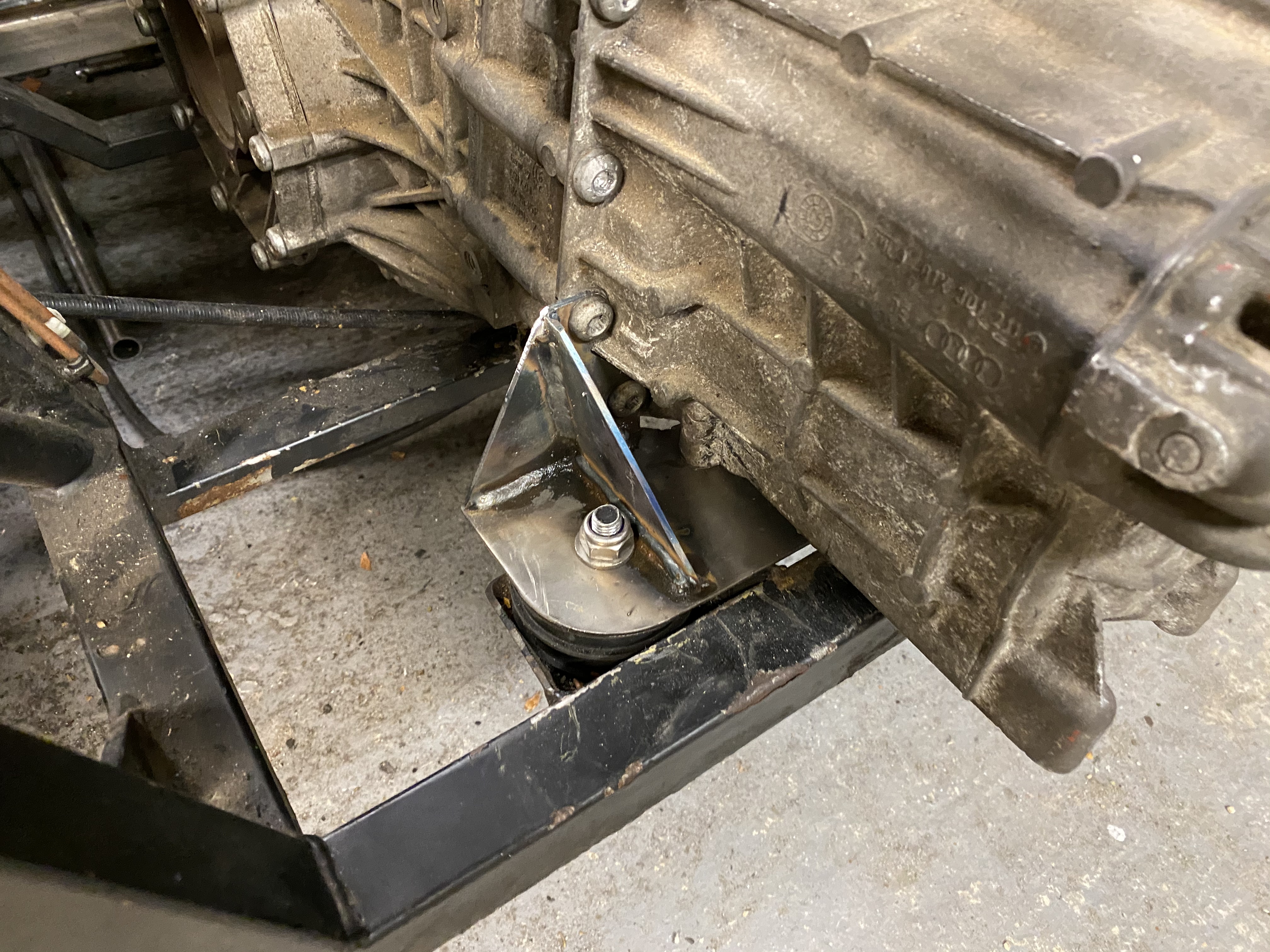
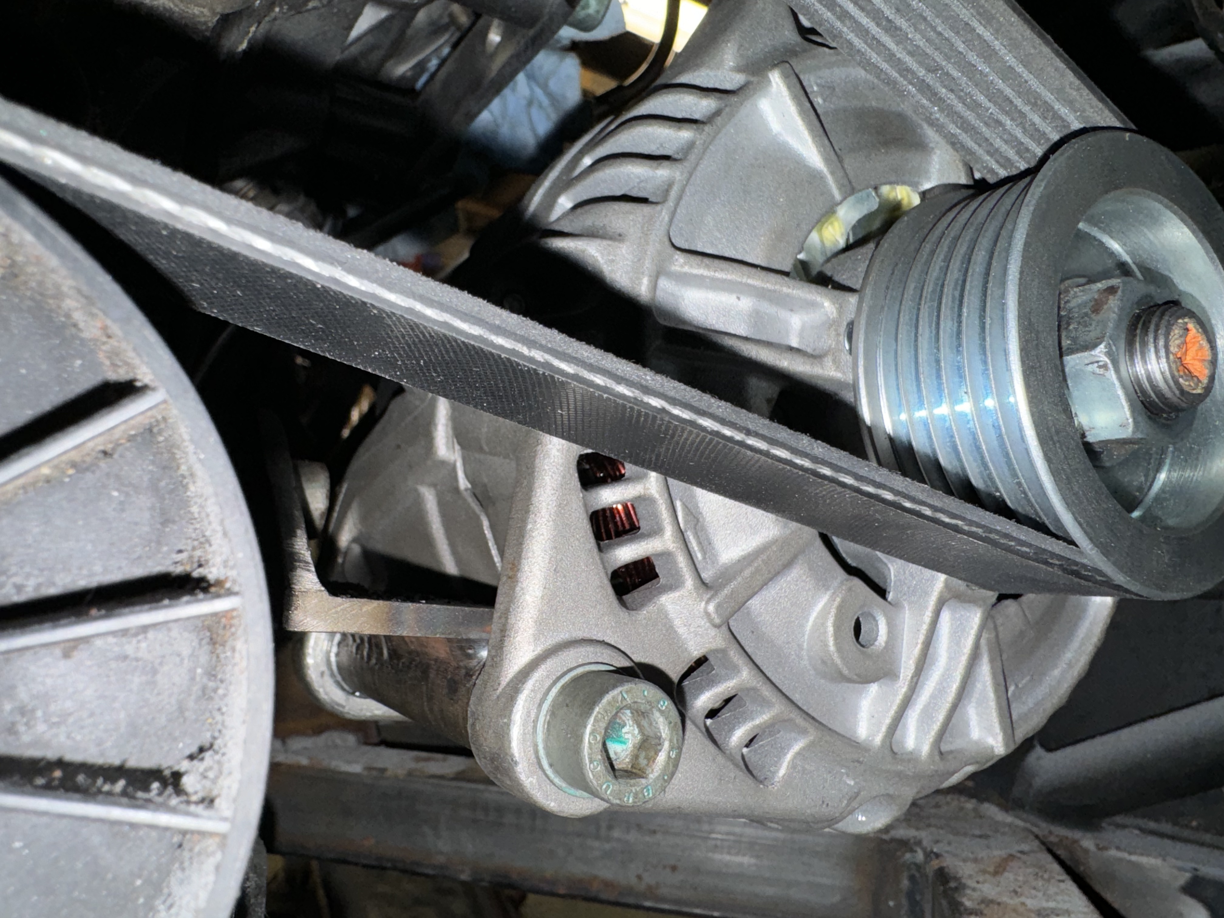
Next step, steel on order to make the engine mounts next, just waiting on order to arrive and will wheel out the welder again, while I ponder gear linkages as well. 
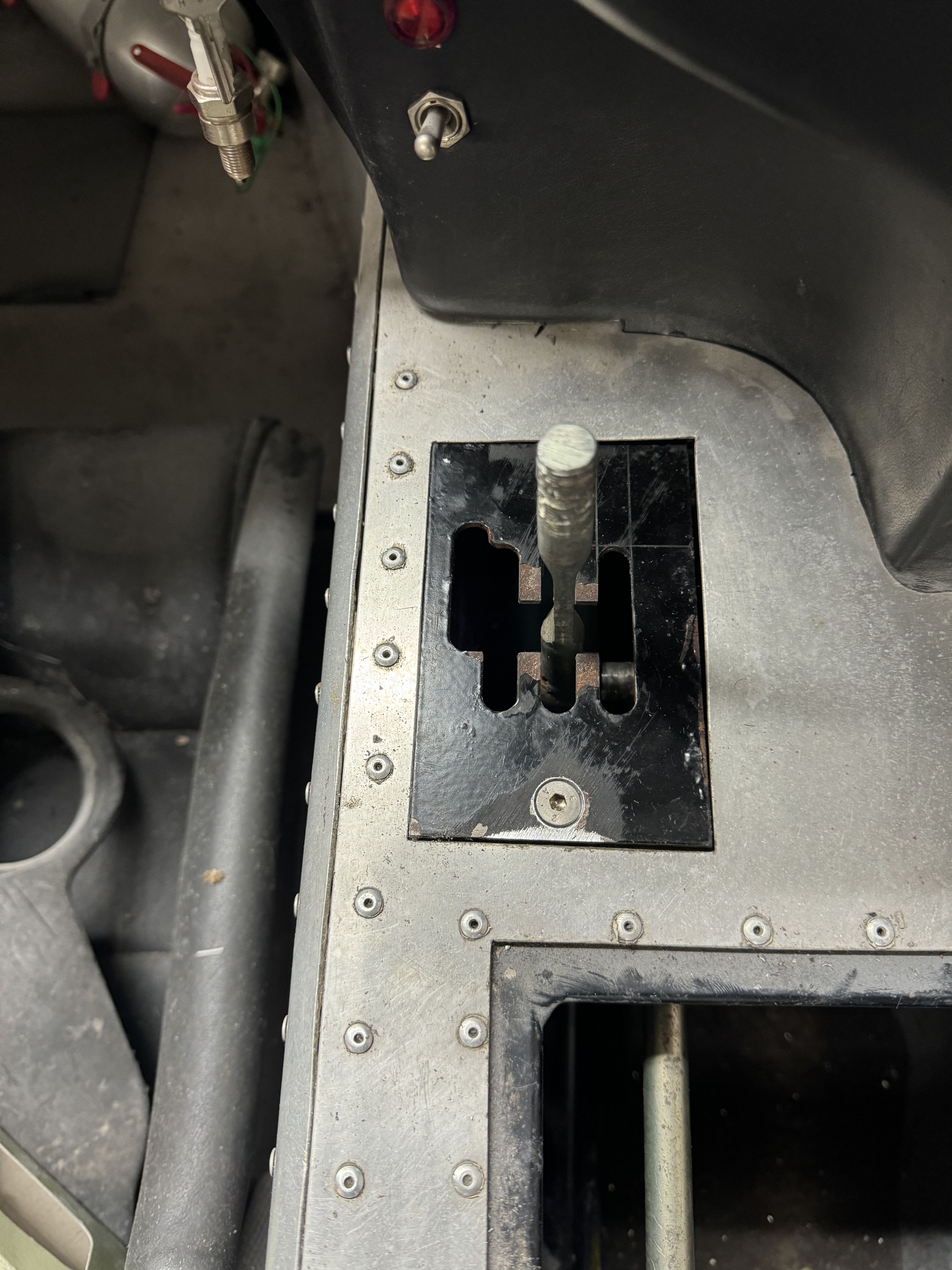
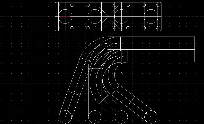
Gear linkage was a proper chin scratcher to try and K.I.S.S, but I had a plan.

Chassis mods were completed along with engine & gearbox mounts. Image Image

Christmas 2023 – Gear Linkage

With a far too long hiatus, I spent some time over christmas doing the gear linkage. It’s just mocked up for now (hence jubilee clips and over-length rods), but works really well and all gears fit in the perfectly. The gearbox end – the “lever” that makes it all happen. Will be shortened eventually: Image 
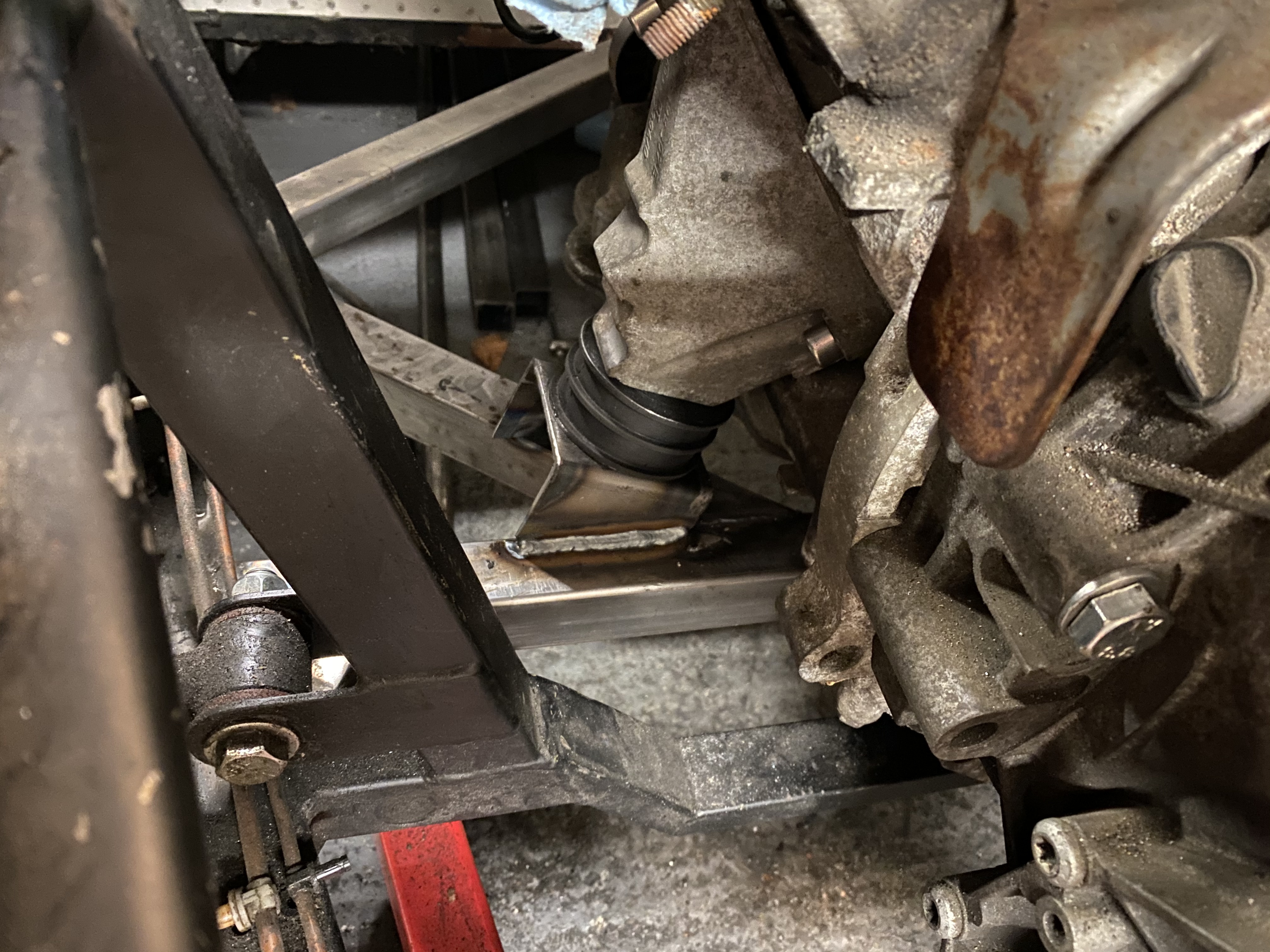
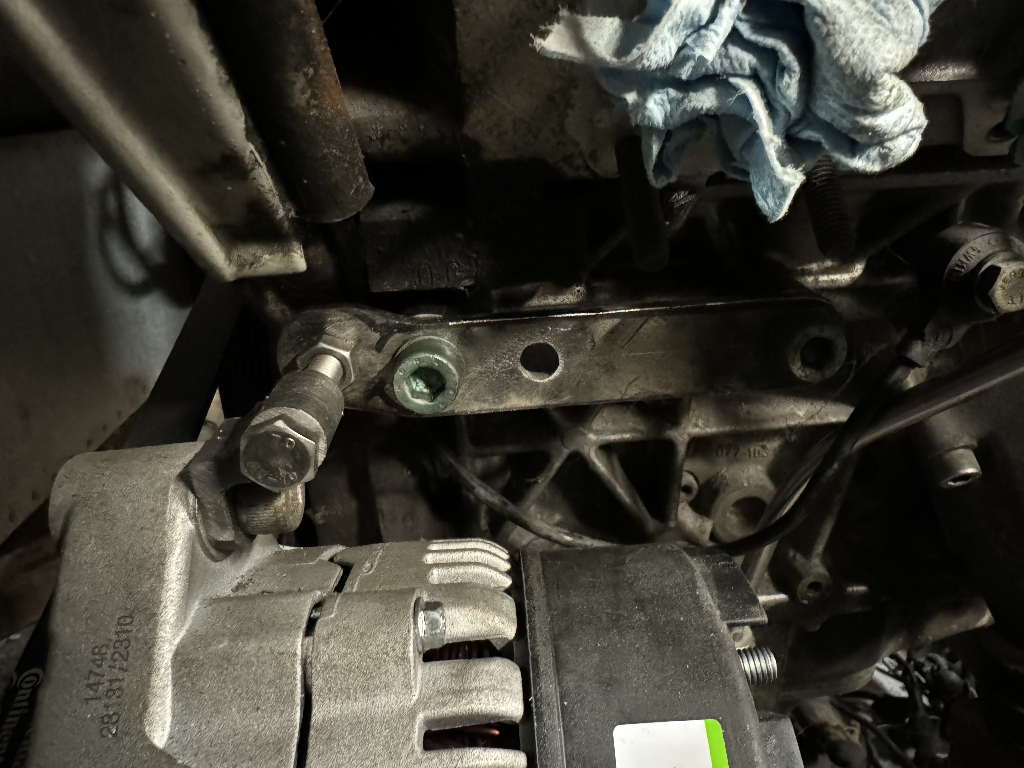
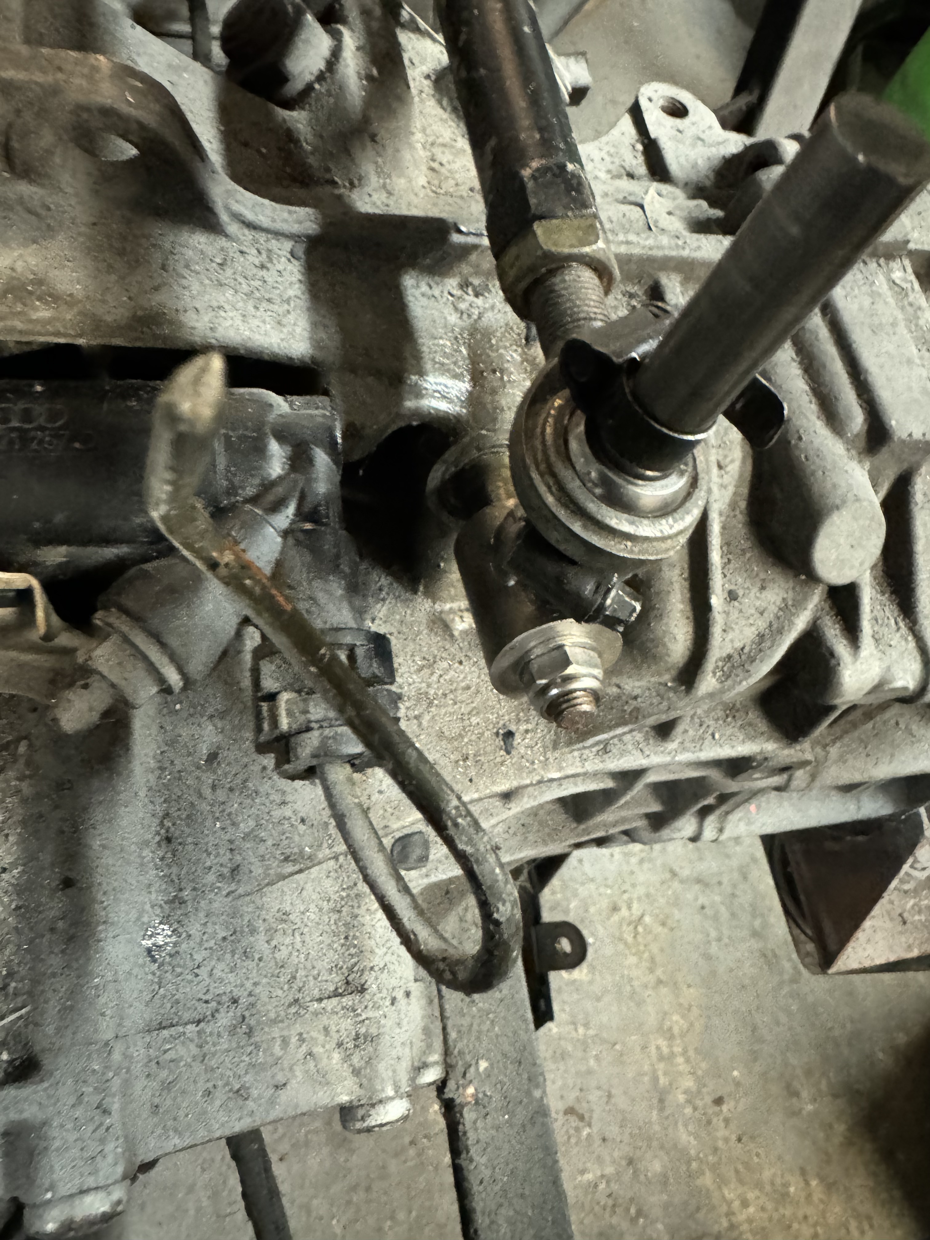
Detail of the shifter bar. I reused as much as I could of the old UN1 linkage mechanism – although the audi box shifts the other way round entirely: Image 
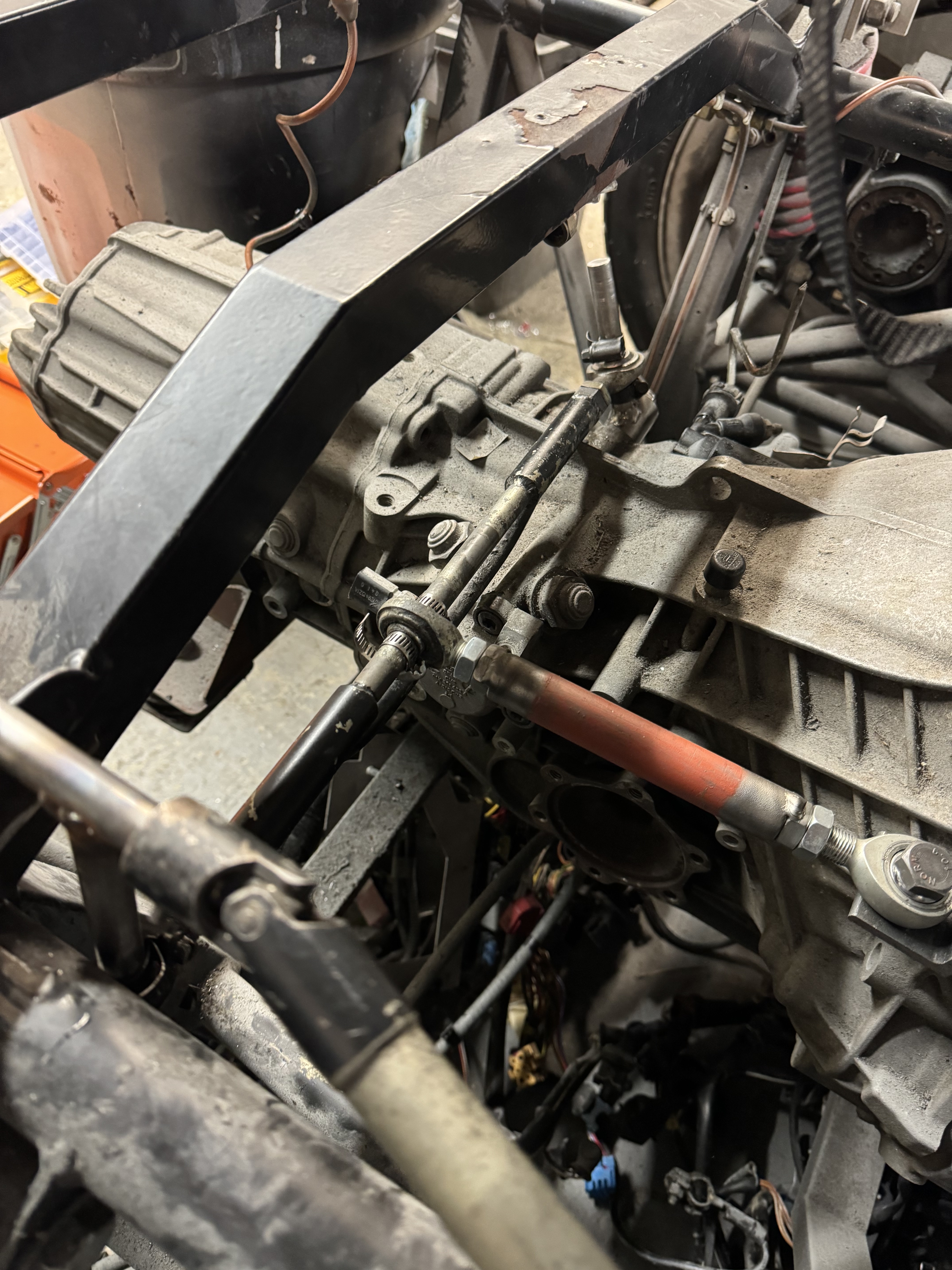
But it seems to work. I cut the old gate around a bit just to see if it would all work, will probably get a nice laser cut one eventually: Image

Driveshafts

Then the CV Joints arrived so I spent a bit of time mocking up the first driveshaft with some 25mm tube. When designing the engine & gearbox mounts, I spent a lot of time making sure the engine was as far forward and as low down as I could make it, which you can see from the driveshaft angles. Image Image Image 
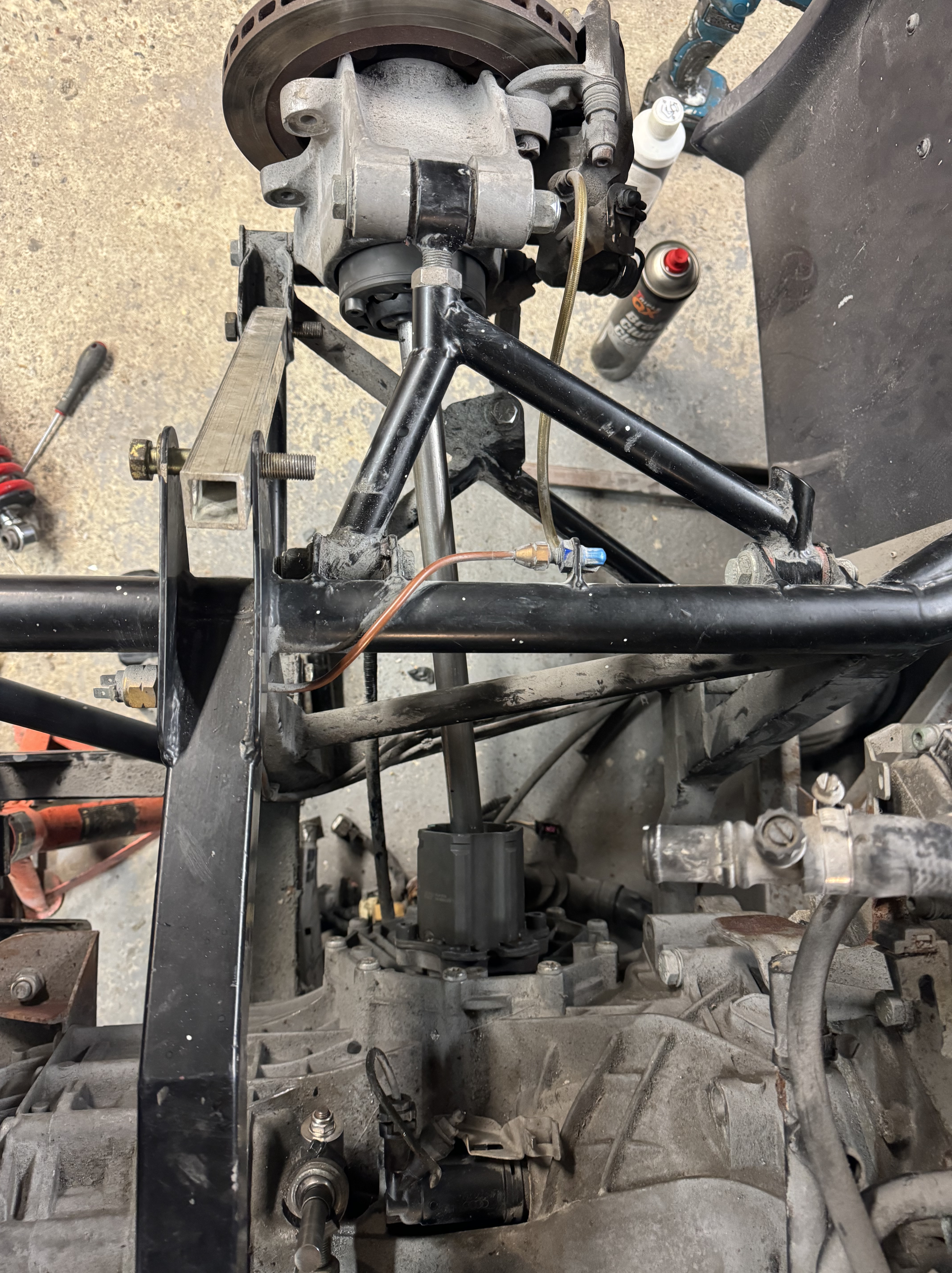
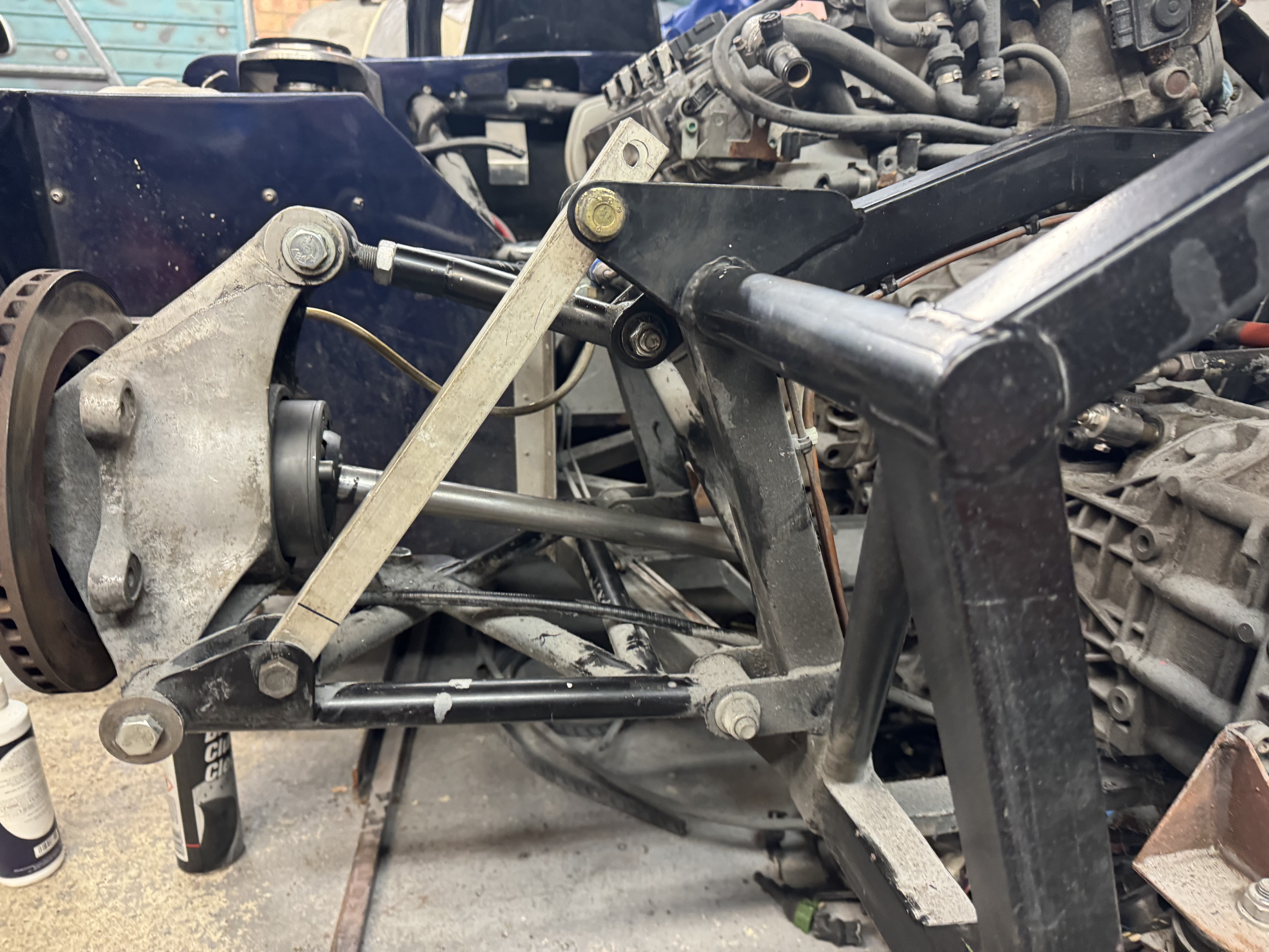
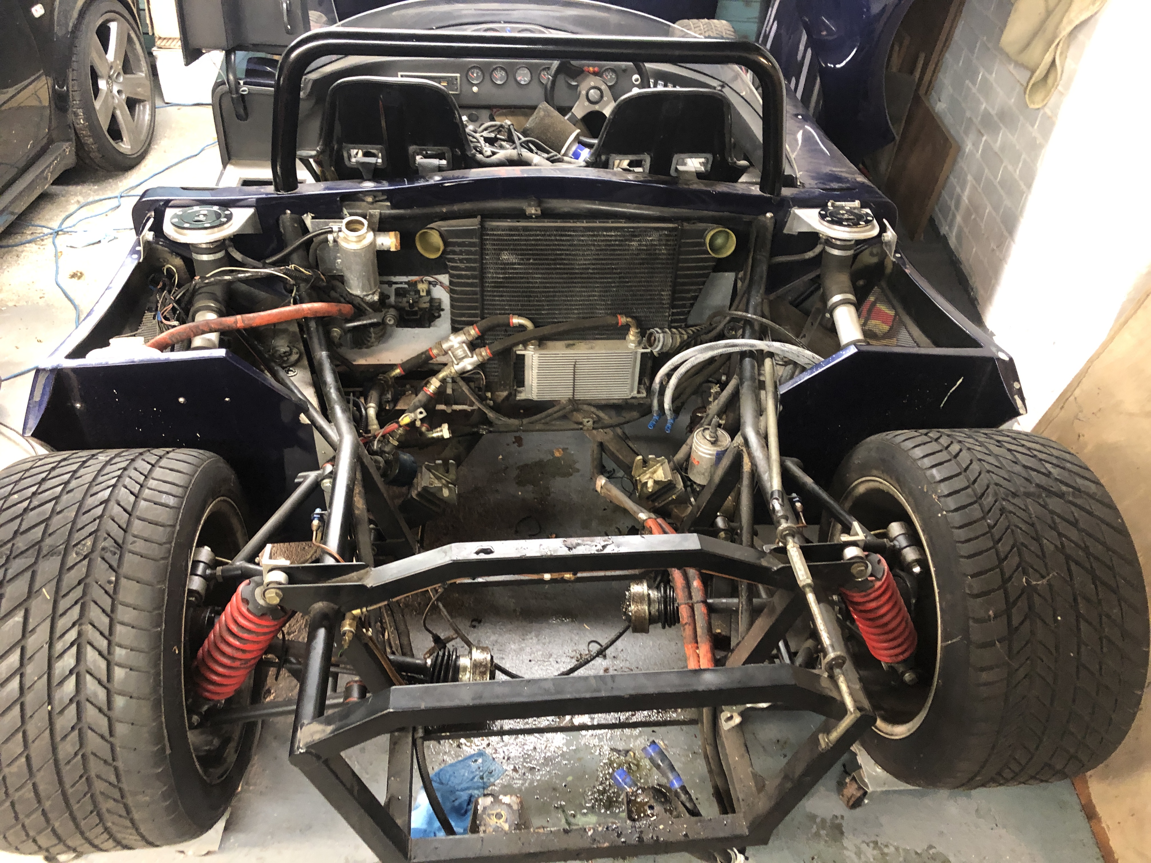
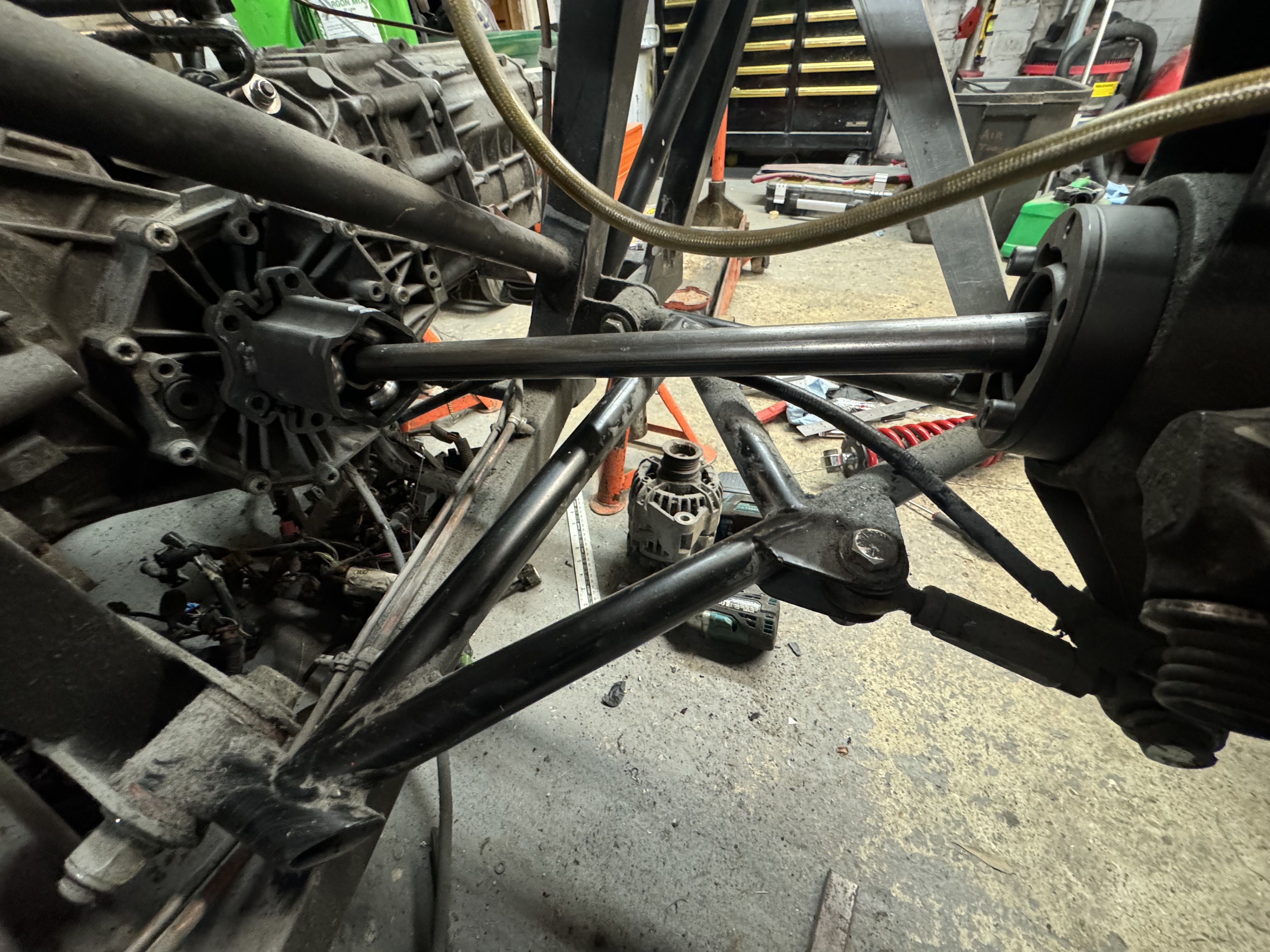
There’s at least 19mm of possible movement (at full drop) on the driveshaft, and 23mm movement resting height, and 22mm on the bump stops. So nothing bottoms out. As of Feb 24, I’m waiting for the driveshafts to arrive. 🙂

Alternator mounts.==

I tried quite hard to mount the alternator on the OS of the car, modifying the original mount. But I’ve actually mounted the engine so low in the chassis that the alternator fouled. Obviously some of what I am doing is inspired by “Hilly’s” Lotus that you can find on motorgeek – esp using the 01x and Audi V8 motors together – and in this case, had to switch the alternator to a NS mount like his. However. my engine mounts are completely different to his – and therefore so is my alternator mount which is a standalone unit. Even considered using a different (smaller) alternator, but couldn’t easily find one that I could be sure would be easier to fit, and I had this one on the shelf already/

I also did away with the automatic tensioner design and have just gone with manual adjustment for the sake of simpler fabrication (this version version 3 already – V1 was modifying the original, then I made a V2 to trial the OS fitment and worked out all the measurements to get it spot on – and then based on lessons from that I did V3!). But I think it all came out OK and if I have to adjust the belt tension every couple of years – no big deal!

OS one that didn’t quite work: Image

You can just about see the bottom mount here. Forgot to take a decent pic of it on it’s own. Image

Top bracket and adjuster. Will clean it all up and powdercoat eventually. Image 
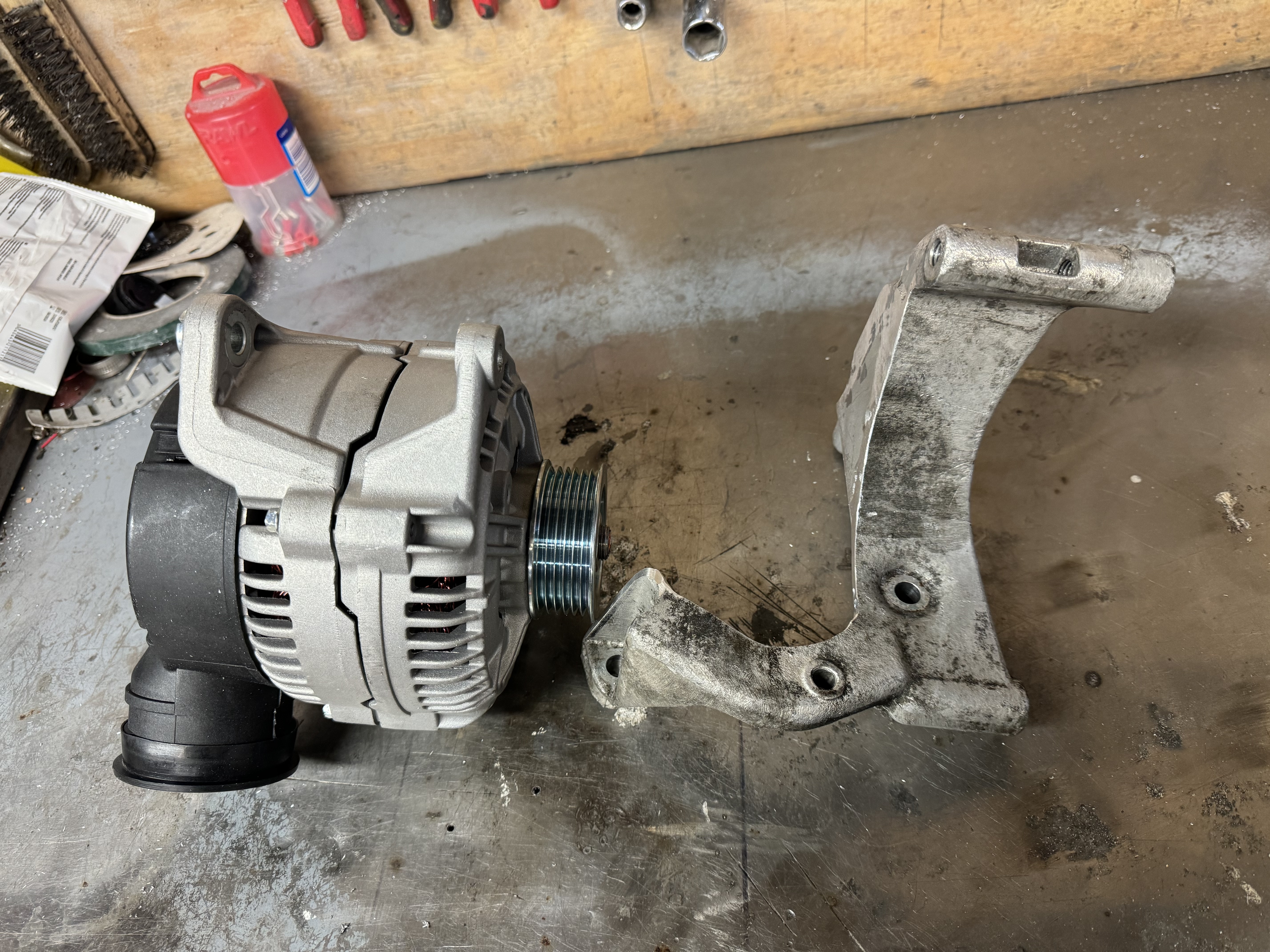
It is pretty much perfectly aligned. 🙂 Image

Exhausts

Exhausts next. I temporarily put the bodywork back on to check everything will fit OK since the spyder has the lowest of rear clam of all the models: Image Image Image

I tried to do something in CAD Image

But quickly hit the limitations of 2D CAD, so just decided to have a go and crack on. I’ve always viewed making headers as “dark magic”, it’s a tight fit to clear the chassis. Image Image Image 
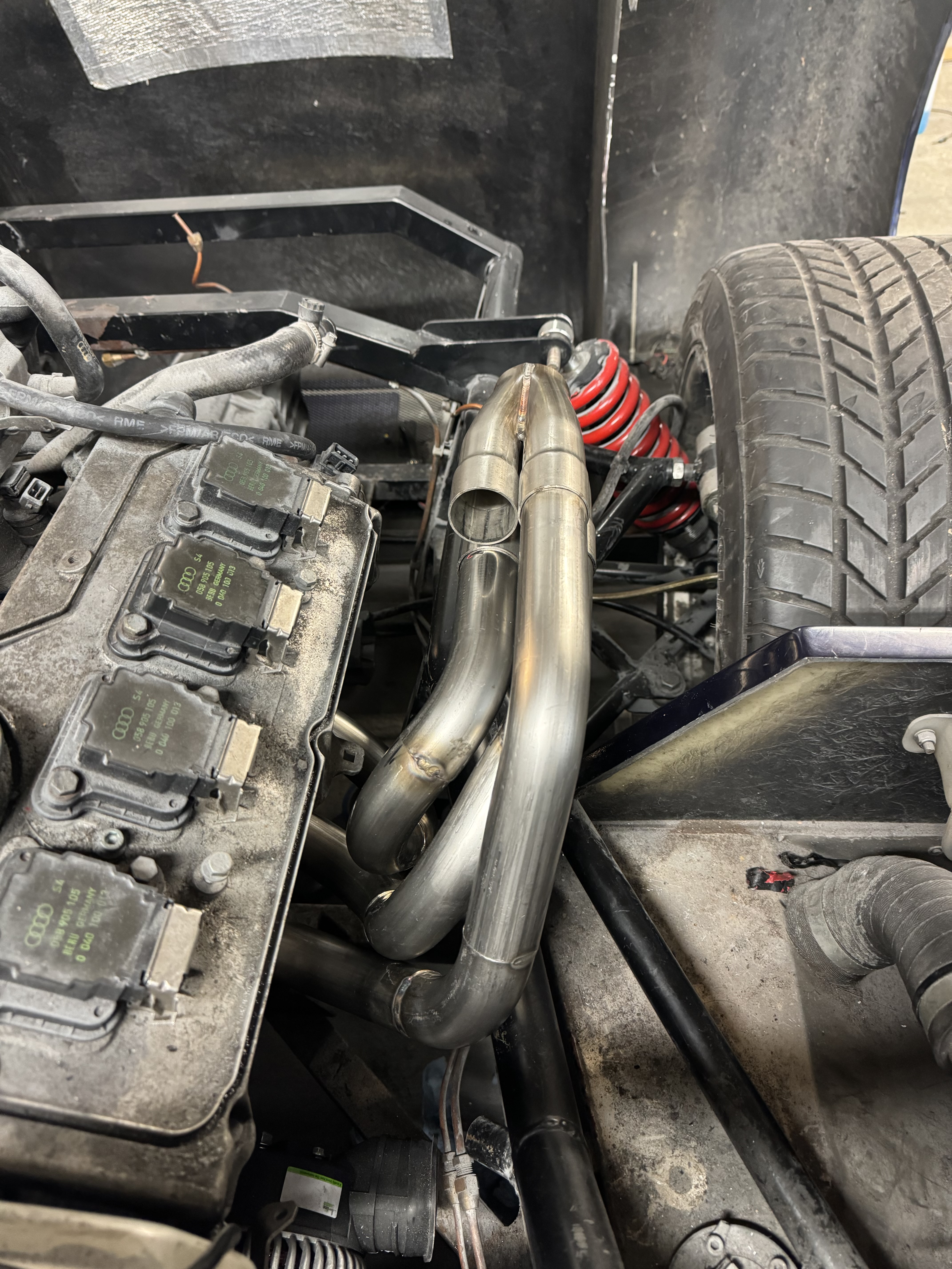
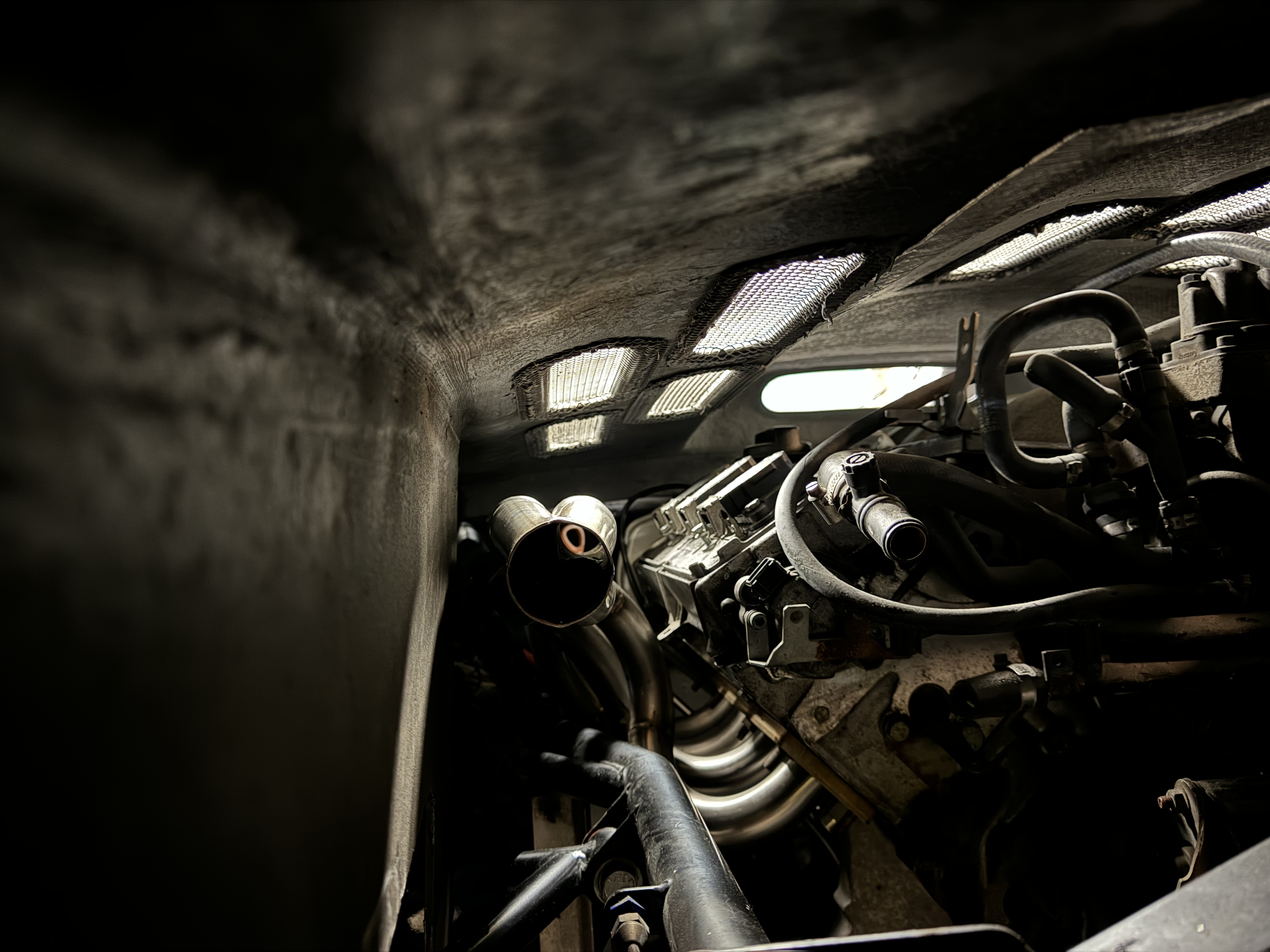
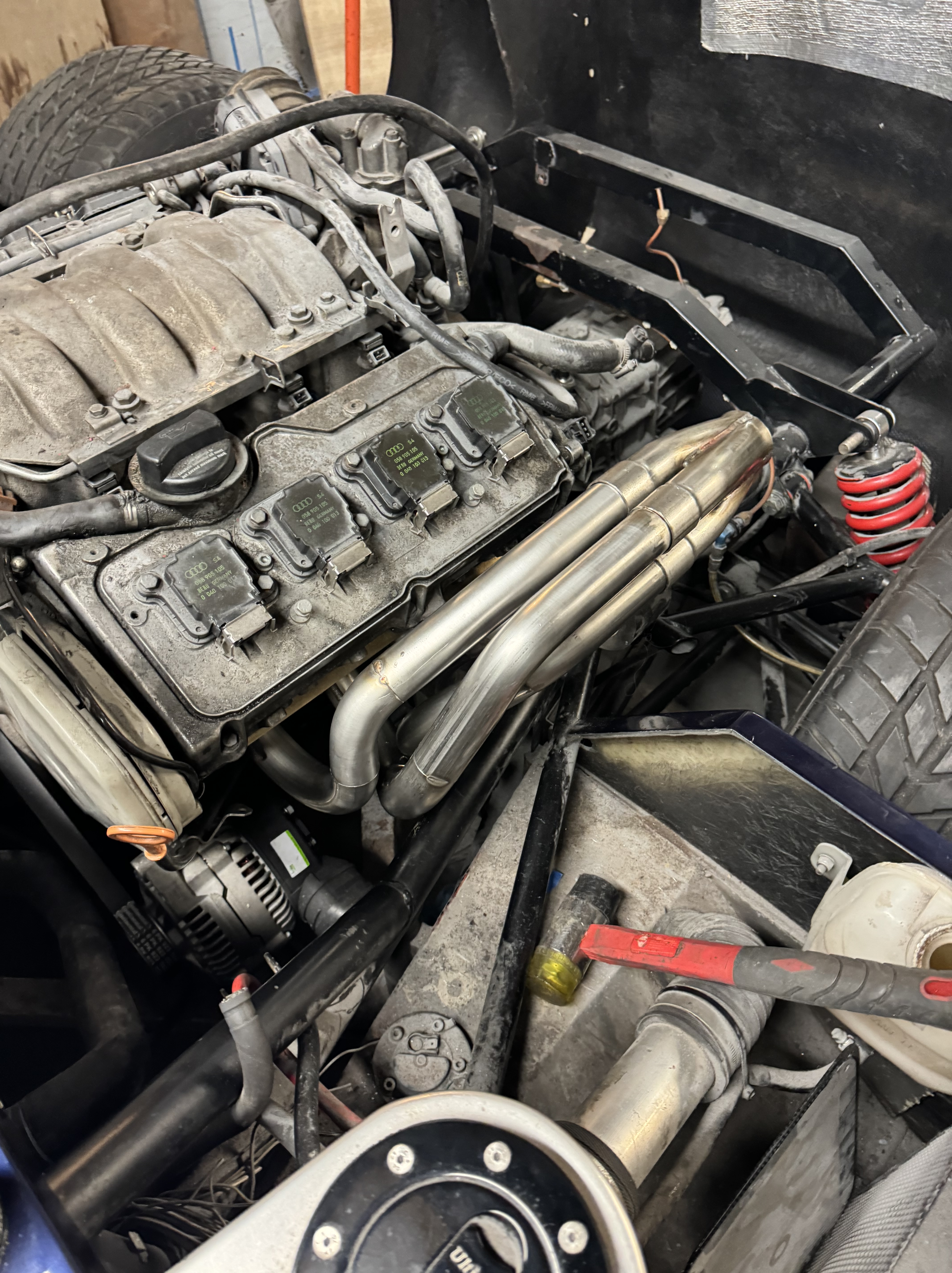
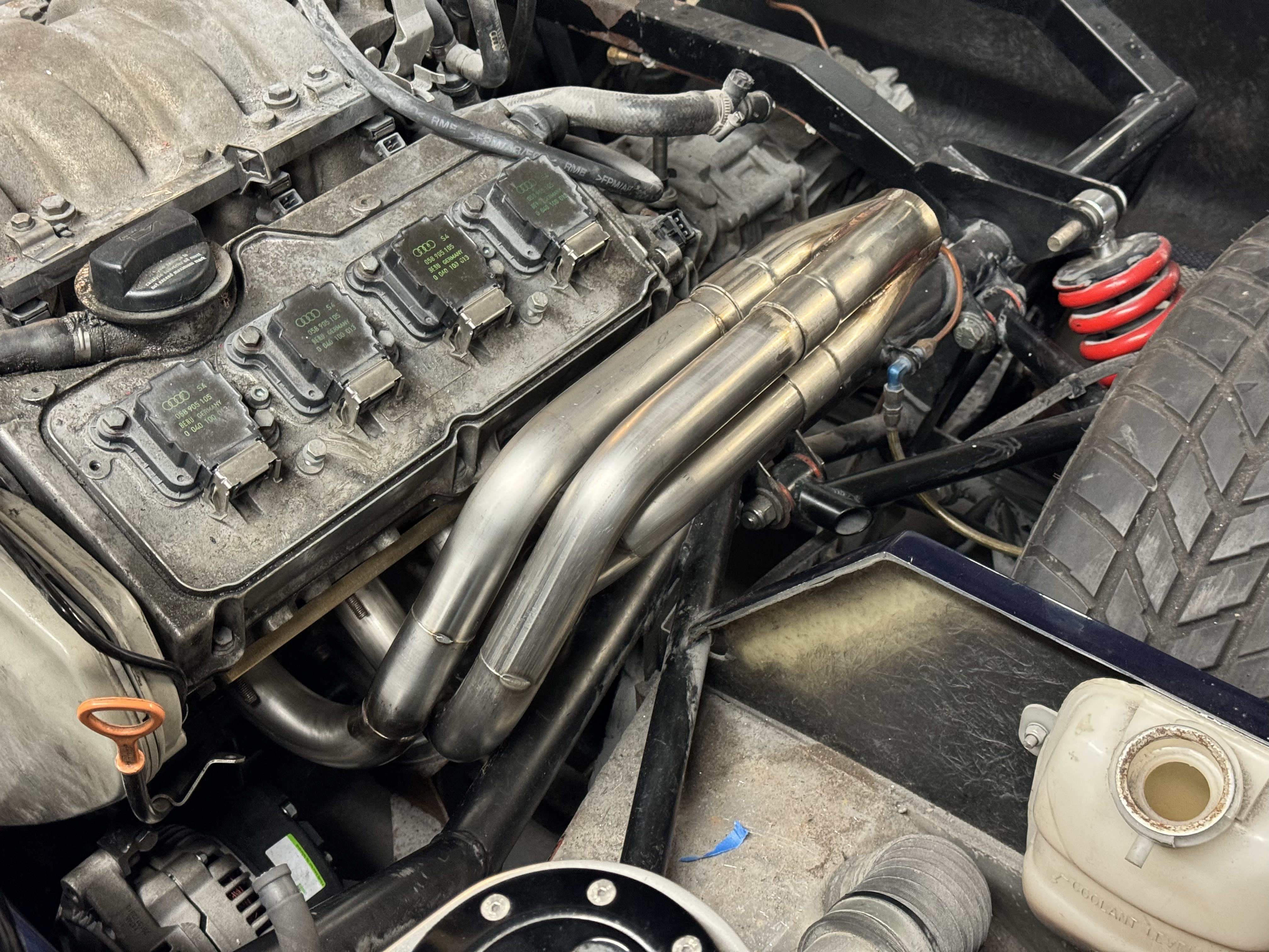
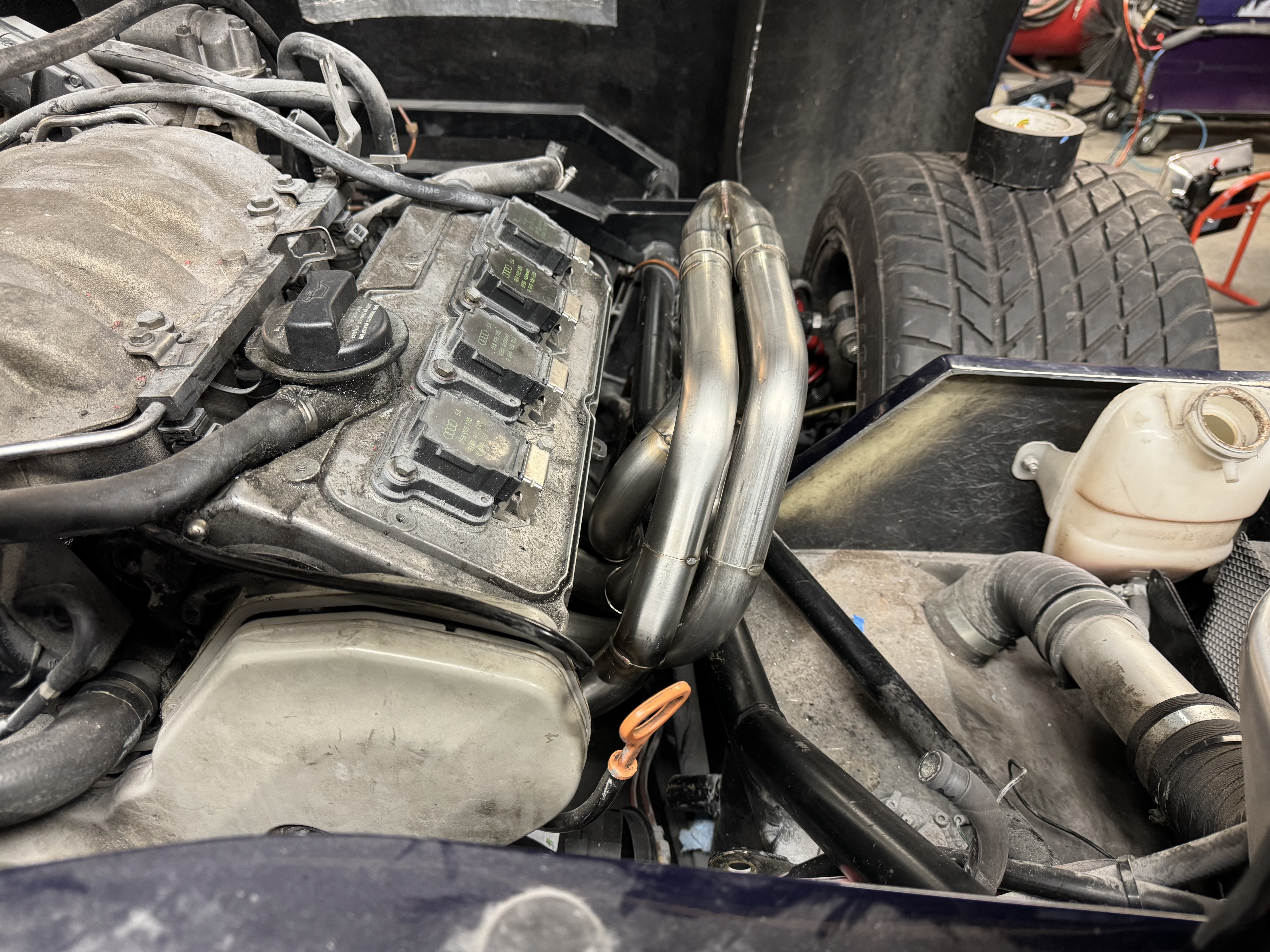
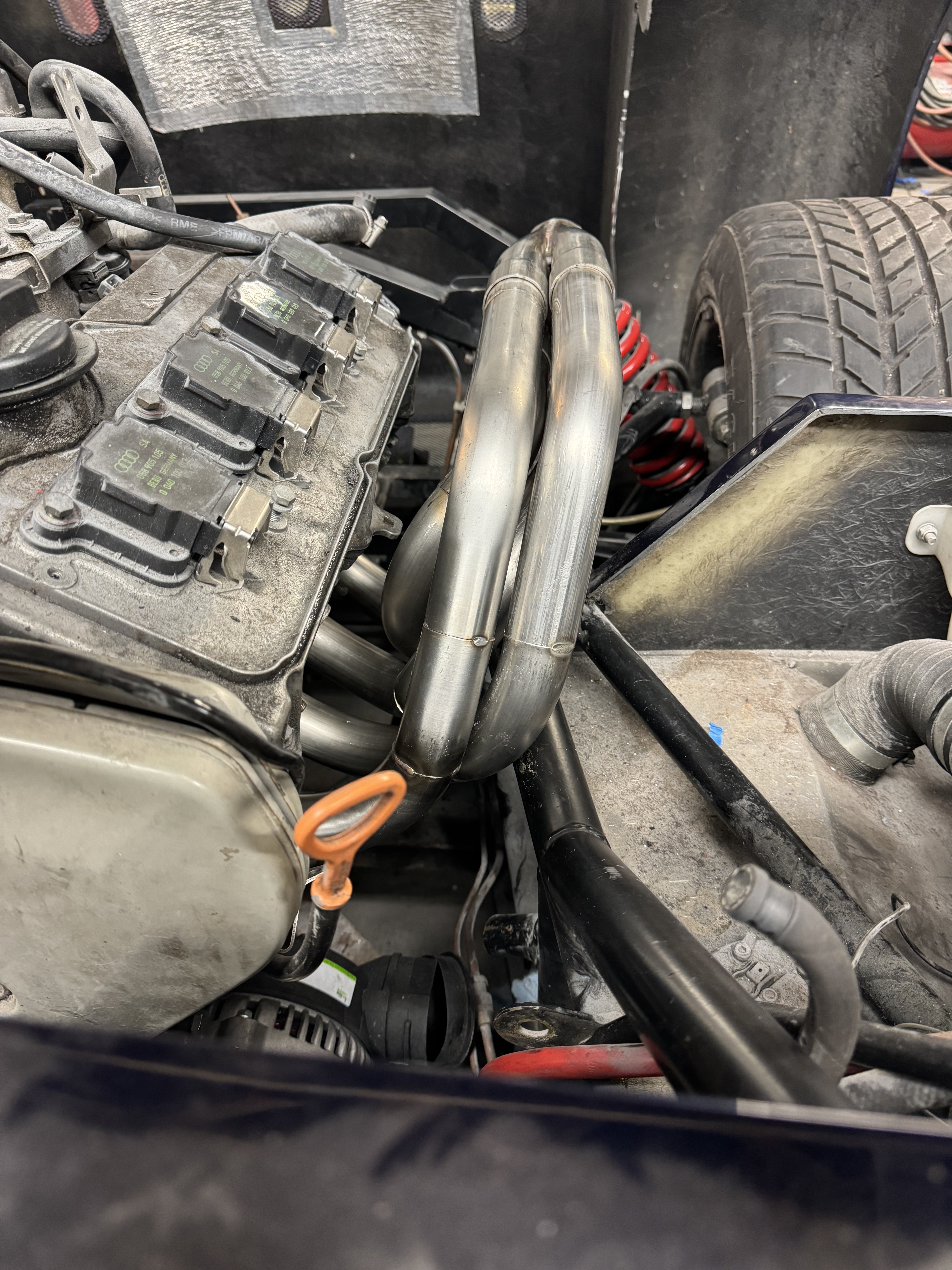
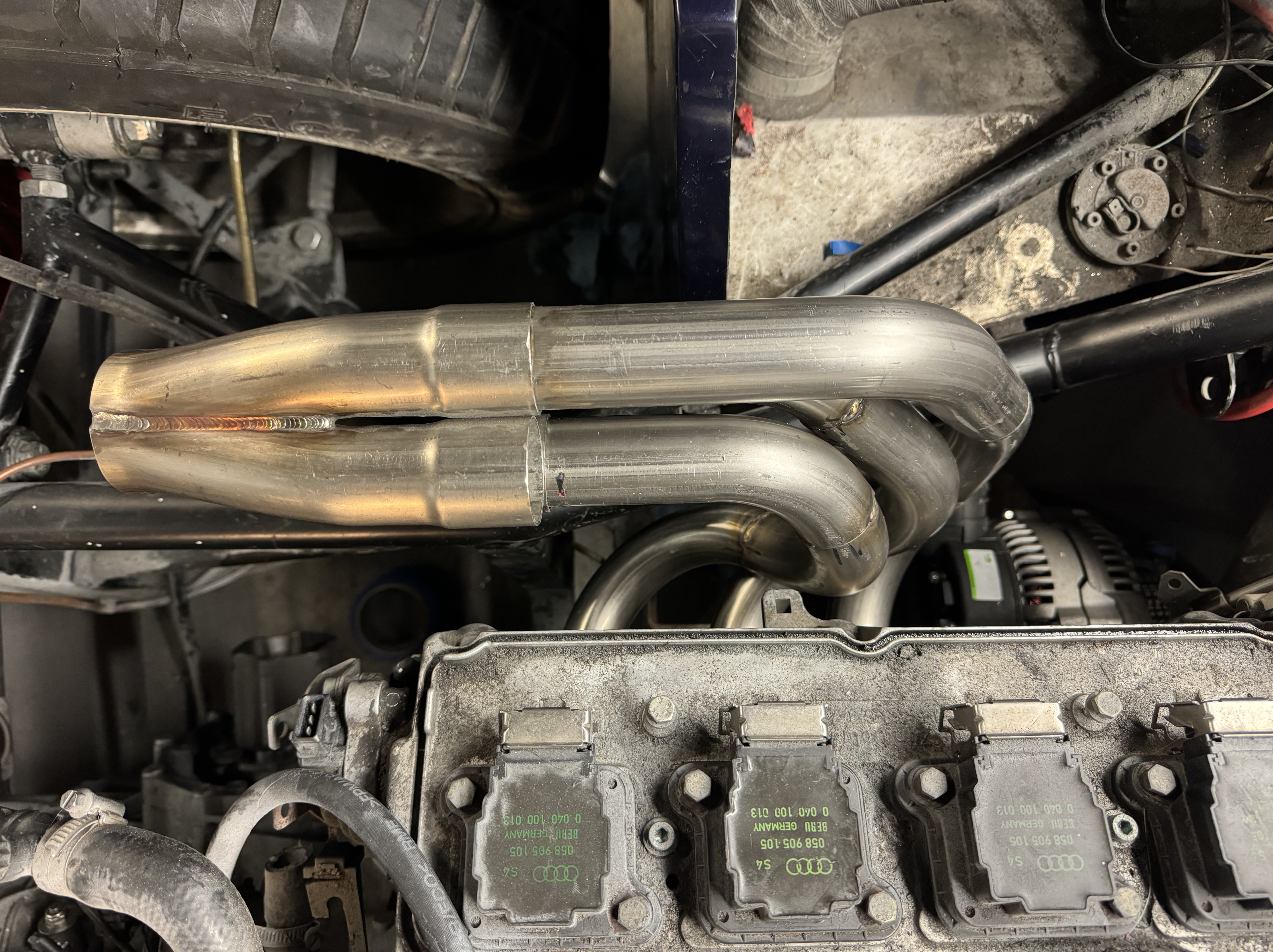
Am happy enough with the first three pipes, but the 4th was not so good: Image

I redid the final one on this side, I think it’s come out much better and tweaked the geometry of cylinder 3 to give a bit more clearance and level out the collector (not shown in this pic) Image Image Image

ECU

I have the ECU already. I’ve done a couple of megasquirts before (that I built myself), but this time while I’ve still gone megasquirt, I like the look of the prebuilt MS3. One the one hand, I’m being a bit pre-emptive, but on the other, it lets me think about “packaging”. Image

Tie Bar

Also made the engine tie bar: Image

That’s progress so far. Next I need to start the offside header, I think I have enough bits in stock, before I can start thinking about the rest of the exhaust system then.

I found my Bravo drive was making an unhealthy sound when running the motor on the hose:

Bearing Whir

That’s not right. Removing the top cap and having a look at the bearings, it all becomes clear:

Infortunately, the water damage also included the bearings in the gears:

So there was nothing for it other than a full strip down and rebuild. This is the pinion gear – every bearing showed some damage, and the big bearings are only available as part of a full kit of gears:

A fairly expensive round of ordering and the rebuild could start:

Carefully put it all back together using all the necessary special tools:

Major bits back in:

Checking pinion gear backlash:

And finally pressure testing it all:

Background

The engine started life as a Mercruiser Bulldog 540, originally part of a triple engine setup on a sunseeker.

Apparently the sunseeker ended up sinking when the engines were virtually new and they were removed and written off by the insurance. The engine then sat in my friend, Tony Davis’ garage for a few years.

When I got the engine, I knew I wanted to improve it a bit to take full advantage of the bulldog “tall deck” block and increased capacity, but without going supercharged or turbo. I always loved the “stack” intake manifolds you see on retro & vintage racing cars and I liked what kinsler had done on some of the mercruiser engines, so I thought this might be an interesting path. I found a small bore hillbore manifold that looked like I could convert it to EFI, along with a set of Eickert exhaust manifolds and mocked it all up:

This looked like it would all fit together, so I worked with Bob Madara (rmbuilder on OSO) to put a spec together. This is the specification we ended up with. It meant I would need to run exhaust dry to the tips, but should also give a nice idle, strong torque all the way up, with peak horsepower at about 5500rpm.

Specifications

Bore4.5″
Stroke4.375″
Capacity556.7 cu (9.1 litres)
Compression Ratio9.56
ExhaustsKeith Eickert Cast Headers
Cyinder HeadsAirflow Research 315cc with Inconel Valves & Anodising
Intake ManifoldHilborn 2 7/16 Mechanical Injection
Fuel & IgnitionMegasquirt 2 V3 running Bank Fired injectors and Wasted Spark ignition
CamshaftCustom Marine Kinetics Grind (see below)
CrankshaftLunati Signature Series
Engine Specs

The camshaft was designed by Bob Madara with the following specs:

Modelling this all in desktop dyno, it looks good. I know the numbers aren’t doing to be “real world” accurate, DD is inevitably a bit enthusiatic on the numbers and is crank, not propshaft, hp. But anyway, this should produce an engine with similar power to the mercruiser 600 supercharged motors and should “just” be OK on a Bravo XR drive. The engine will never be dynoed to verify, but it’s nevertheless good to see some nice high volumetric efficiency numbers (we have all the head flow numbers entered correctly) on a big block chevrolet motor.

This set the recipe, so a few wise purchases later, along with having the block bored out slightly and a crank journal machined, I was ready to start assembling it all.

The Build

The block was bored from 4.44 to 4.5″ bore, leaving enough meat still in it for a rebore in future if needed (that would then make it a 572 as well). After cleaning all the block very carefully, new cam shells were pressed in to the block:

And the bottom end assembled:

so far so good

Next the cam was installed and timed:

And the heads, along with the scorpion marine duty roller rockers:

Including using test springs to work out that stock length pushrods were OK:

And the intake manifold:

It started to look decent:

And eventually it all came together pretty well:

Lessons

I learnt quite a few things duiring the build, here’s 3:

Avoid the single piece steel core sump gaskets – of it you do use them, use them carefully. I had a leak where one was a bit too thick and didn’t compress down properly – which meant engine out of the boat again tp put a traditional 4-piece sump gasket in.

The 140 amp single V-pulley alternators from DB Electrical are excellent value for money

Always use the bypass hose on the circulating coolant pump. I originally rigged my engine without this, making the block “full flow” – which also works for the full flow heat exchanger I have. Bad move. Without the little bypass hose on the reciculating pump, it generates enough back pressure to blow the core plugs of the engine. I wouldn’t have believed it if I hadn’t seen it. One popped out at fast idle on the hose – I assumed I had not put it in properly. One then popped out when I was out on the water – so I pulled the engine out to investigate properly and found that a 3rd would have come out, except it had wedged itself against the engine mount. Since re-installing the bypass hose, all is fine again.

When I was building the boat, I wanted to make the boat as retro as possible, while also putting some decent modern technology in to it. I looked at the Kinsler and Hilborn EFI setups and they are lovely, but I wanted to see if I could package it a little tighter and hide the injectors between the stacks.

I spent a lot of time searching until eventually I found a hilborn manifold that I thought I might just be able to squeeze some EFI injectors in to.

This the manifold in its original installation :

And as I got it , looking in generally good order:

There were 2 main challenges:

  1. To run an EFI system, I wanted at least some MAP (pressure) feedback to the ECU. At wider openings, vacuum collapsed quite rapidly on ITB setups, but for idle & off idle, I wanted a vacuum signal
  2. Could I find some injectors that fit

Vacuum “Plenum”

I decided that the holes already in the manifold for the fuel meter would make good mounting points for the plenum:

And machined up a block of aluminium to fit:

And I then made up a copper pipe & union running from each intake tract to the plenum:

This was the Mk1 version, since then I have put better unions on the manifold end. Overall, it works. I never expected to get much vacuum signal for the EFI, but I get some and it helps give me a nice smooth idle:

Injectors & Fuel Rails

I decided to get a set of Bosch EV6 “Pico” injectors from Summit, since I thought these stood the best chance of fitting https://www.summitracing.com/parts/fms-m-9593-lu47

After removing all the mechanical injector equipment and then carefully reaming out the mechanical injector mounts, I can “just” about squeeze a full set of EV6 injectors in, inbetween the banks

With the fuel rails mounted on top. It is a tight setup though, trying to squeeze injectors, fuel rails, TPS sender & fuel regulator in. But it all fits and it all works:

Exhaust Upgrades

After the last run, it was clear I need to put some effort to quietening things down a bit around marinas and so forth. My initial plan was to just downrate the camshaft slightly – sacrifice a few mph top end and be able to run a wet exhaust – however rmbuilder was reluctant to spec me an alternative camshaft and instead recommended mufflers. So a fair bit of hunting round, eventually I found that Gil mufflers can run dry, so I set about making some new tailpipes that would fit the gil mufflers, plus also let me adjust how much water goes in to them.

At the same time, also wanted to reduce reversion. Original plan was to have a large crossover pipe between the banks – since the major point of reversion is due to the uneven firing cycle between banks. Originally planned to have a full 3.5″ inner bore pipe mounted immediately after the collectors, but eventually I realised this was impractical.

Also wanted to have a flange between the collector/manifold and the tailpipes – to give me a better mount point for the O2 sensors and also to have a EGR check valve in – this is another idea, to have an EGR type check valve in so that at idle, rather than suck exhaust (water) back in, fresh air is pulled in via the check valve. Don’t need a huge amount of flow here, just enough so that at idle there’s a little less reversion.

The flange idea also means that as I try different packaging/ideas out – I just need to make a new flange, not a whole new tailpipe each time!

Exhaust Flange

Part 1 was to make the flanges and see if this plan was viable. I needed an aluminium flange, 50mm thick,

Unfortunately, nobody wanted to make me one of these, so had to make it myself.

Started off with a couple of bits of 50mm thick aluminium:

And then slowly using the biggest holesaw I could get to work, cut a hole in the middle:

That was enough to then get it into the lathe with a boring bar:

I think they came out OK:

Tailpipes

Next it was time to build new tailpipes to fit both the flanges and the mufflers. I had new stainless 316 flanges laser cut from fractory, so the first steps were easy to mock up the inner tubes:

However, if you’eve ever looked at a dry tail pipe boat, often the exhausts look asymettrical coming out the back of the boat through the transom – because the exhaust manifolds are offset slight (one bank of cylinders is about 3/4″ forwards than the other, which messes up the angles). This meant that while I could have one bank with a straight tailpipe, the other bank would need to be adjusted to make sure the exhausts are symmetrical on the transom). This took a lot of backwards and forwards for what appeared like a small cut. in the pipe You can see in the below pic that I’ve already welded the inner & outer to the flange, along with the water dump pipes fabricated and welded on, along with half the outer.

It was also necessary to have the flanges bolted to something pretty sturdy to stop them distorting when they were being welded:

And I’m still a beginner at tig welding, but I think it came out OK:

Next it was time to weld on the last bit of the outers (which then means I also need to remove the manifolds to install & remove the tailpipes – aggro!)

Then needed to make some clamp water dumps for out the back. The “idea” is that the mufflers get cooled externally from the outside to avoid burning them up too much – pics below will show:

Final install. I think they came out OK. Hope it works! this pic is with the flaps closed.

Oil Leak

Also noticed a small oil leak from the sump last time I ran it. A bit of googling tells me that the “modern” single piece oil pan gaskets are notorious for leaking as they’ve a bit thick & rigid, so yet again, engine out:

And then when I drained the oil, I found a couple of drops (literally) in the oil. That’s not right! So I pulled the intake manifold off as the most likely culprit. I hope I found it:

So a bunch more work redoing that:

29th July Update

Finally got a chance to test all the work out. Everything seemed to work well, oil leak is fixed and with the mufflers closed, it’s quite a lot quieter. No high-speed footage unfortunately, but you can hear the idle is now tolerable, similar to a wet silenced engine. Not quiet, but acceptable. It currently has a 3mm water hole into the mufflers, primarly to let the tips drain down, but it also helps muffling. Once everything settles down and all the efi map is tweaked, I’ll add another one that’ll help silencing (water is the best silencer) and then review it from there.

Certainly not a new purchase, I bought it in June 2008. But it has recently been the subject of a bit of attention over the last 12 months.

What Is It?

A 1989 Factory 90 V8 Country Petrol.

I bought it because I previously had a 1981 Series 3 Stage 1 V8 which I got rid of many years ago, and I fancied another one. I’m not a particular Landrover fanatic like many are – but I do like a V8 engine under the bonnet. So I wandered in to Safari Engineering in Yateley and asked dave if he knew anyone with a 90 V8 for sale. It just so happened he did. The blokes nickname was Jesus and he used it as his dog walking car, until the engine had expired (little end failure). Now, a wet dog is a smelly thing, so it took a lot of time and effort, mostly by jetwashing the inside of the car, to eventually get rid of the smell of dog. But the name persists and it is known as “The Dog” in our household.

Over the years, have done many many jobs on it, when I first bought it I replaced the engine, going from a broken 3.5 carb to a 4.0 EFI, which I then later put a megasquirt on. Various welding jobs over the years.

A few years back:


And sometimes I do work on it:

This time it needed a little more work, so I gave it a fairly decent going over. I wanted to fit rear seats to it, but proper, forward facing ones with 3 point seat belts, not the sideways facing ones only with a lap belt.

On inspection of some of the bodywork in the vicinity of where the seatbelts would mount, I realised some work was needed:

The lower panel – easy to replace with a stock item from landrover, but that upper bracket is not available, so I had to make one.

First I made a template in CAD:

And then cut it out in steel:

I think it came out well:

Bulkhead Removal

As is often the way, I then started to get carried away, so I then removed the bulkhead, replaced with a bulkhead brace bar, to give a lot more room in the interior and make it easier for the kids to get in and out:

Body Cappings

And carried on replacing any rust as I found it:

Brand new cappings from Landrover:

It was starting to come together quite well:

Leaky Sunroof

The sunroofs are well known for leaking, so I decided to remove the sunroof entirely. Even though the roof is a bit old and dented, I still wanted the new panel to sit flush and look tidy:

A nice sheet of 1.5mm NS4 ready to cut:

Seemed to go OK:

And fitted nicely:

Quite happy with the end result:

Bulkhead Repairs

At this point, I was looking at the bulkhead. I knew the top corners were a bit rust and I’d put some patches on them a few years back. I decided it was time to do them properly. It was fairly scary how rusty the structures were underneath once I started cutting:

This took a fair bit of work to make:

But came out pretty well. I did both sides, naturally:

The Repaint

As I then suffered a severe bout of scope creep, I decided that as I’d just replaced a bunch of rust with steel, it just wouldn’t do to leave them unpainted. But what colour and how to do it. I decided it might be fun to learn to spray a bit. I did learn a bit – the main lesson being, it’s well worth paying someone else.

Nevertheless, it came ouf OK, although I intentionally did it in white because that’s more forgiving of my errors. All done in cellulose. Would have liked 2-pack, but I don’t have the booth or breathing equipment to do it. Felt like I spent forever filling and sanding – and even then, it’s not a great job!

Slowly but surely, things progressed:

Gradually it started to look like a landrover again:

Apple Carplay

One thing I like in cars is to have apple carplay, plus I wanted front and rear hitchcams to help me line up a trailer first time. But I don’t like the bulky dashboard solutions mosf of them end up with, so instead I found a suiper compact 5″ screen carplay unit which I fitted along with some auxiliary switches:

The slighty curveball here was that the LT85 gear stick is further forwards than the other variants, so I had to modify the gearstick to make it fit:

Somewhere during all this I replaced the gearbox too with a refurbished LT85 from Ashcrofts.

Rear Seats

Finally I was in a position to start fitting the rear seats, using the exmoor trim Loc N Fold ones. They’re really good.

Cab Heat

I also decided to add another heater to give a bit more winter heat in the cab:

Oil Cooler

And made some proper brackets for the oil cooler:

Finally

So with it all back together, here’s where we are today. Still on the original chassis, I will replace that one day, and I need to do new roof lining and carpets in the cab. But looking smarter than it was, I think:

Aria Resorts St Helens caravan site is on the Isle of Wight. At the end of 2018, all customers on the site were not offered a pitch renewal and everyone had to move off the site.

It wasn’t handled by Aria as well as it could have been at the time – but the site was well overdue redevelopment and it didn’t really come as a shock – although it was still a disappointment; we’d hoped for at least one more year.

2 Years later, we’ve just bought a caravan with the same company that threw us off last time. Why would we do that?? Are we mad? Possibly yes, but the reasons are also pretty compelling.

Location

We love St Helens & Bembridge end of the island. There’s lots of vans in many locations on the island, but we like that it’s:

  • Walking distance from Bembridge Harbour (especially Brading Haven Yacht Club, The Best Dressed Crab)
  • A small park – 92 Vans total, not crammed in, nice and secluded with a good bit of greenery.
  • A quiet park – Some of parks have a lot of laid on entertainment. We don’t need this – we like peace and quiet and doing our own thing.
  • Walking distance from Bembridge beach
  • A short walk from the green at St Helens

This is an honest photo (taken from trip advisor) of the park, in this case, looking up the middle of the park at some of the lodges. Not your run of the mill, crammed in, holiday park:

Cost

It’s important to consider not just the upfront cost, but also the ongoing costs.

When we compared costs to the nearby Nodes Point, their pitch fees for what we considered to be one of the worst pitches on the site (overlooked by the bar) – £7,000. St Helens £4,500.

On a like for like basis, the van costs are not disimilar – but over 10 years, Nodes point worked out in excess of £25,000 more expensive for an inferior pitch. Parkdean sites do lay on a lot more entertainment, have their onsite restaurants and so forth – so you do get more for the money – but for us as owners, it wasn’t value.

The Van

We liked the van – a Regal Seascape. Vans have come on a long way over the last few years, and Aria were offering a central heated, plumbed in (gas, water & electrics) van also with double glazing. It’s a great van, well made and has a great feel to it.

The Agreement

You read horror stories from some of the pitch agreements. The one we signed was reasonable and fair, plus any Steve (The sale manager we worked with) was open to tweaks to get it just right.

The Sale Process

There is no pressure. Steve is much more interested in making sure the location & van are right for you than squeezing you in to a sale you’ll later regret.

Summary

The proof is in the pudding – since we bought, we’ve not had a hint of buyer’s regret. Quite the opposite, we look forward to every visit and can’t wait until we’re back down there again. Thank you Aria for reinvigorating the site and bringing it back to life again.

Autonomous Data Warehouse – the new kid on the block. But does it really live up to the hype – will it make your analytics platform run faster or is it just more sales hype?

The most common question I get asked is “should we look at ADW”.
The second most common question (once I’ve said yes to the first one) then is “why”?

Let’s see how it really performs with some simple, reproducable tests that you can compare to your on premises databases, too.

(more…)